Installing, Pole or rail mount – Airmar GH2183, GPS & Heading Sensor User Manual
Page 8
8
Installing
CAUTION: The alignment tab on the sensor must be facing forward and parallel to
the centerline of the boat/vehicle for accurate compass readings.
CAUTION: Be sure to use the correct parts for your installation. Do not use the
flush mount parts (gasket, part B) to mount the receiver on a pole. Using the
wrong parts may allow water to leak into the unit.
CAUTION: If you use a thread locker, use teflon pipe thread tape. Do not use a
liquid thread locker as it may weaken the plastic, causing it to swell and crack.
IMPORTANT: Plan the cable route between the sensor and the display and/or
network before beginning the installation.
Pole or Rail Mount
The nut assembly supplied has standard marine 1"-14 threads that can be
screwed to a standard marine antenna mount, extension pole, or rail-mount
bracket. Before beginning the installation, plan for securing the pole/rail bracket to
the selected mounting surface and purchase all the necessary hardware. It may
be helpful to fasten the pole/rail bracket in place before proceeding.
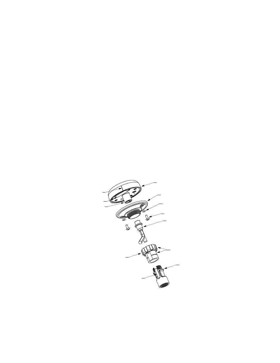
1. Remove the label from the sensor unit’s socket (see Figure 2). Fasten the mount
base (part C) to the sensor unit (part A) with the two machine screws and lock
washers supplied. The torque for the screws is 1.35Nm.
socket
serial number
alignment
tab
nut assembly
sensor
captive
nut
connector
a.
b.
cable
slot for
cable exit
side-exit
mount base
sensor unit
lock washer (2)
machine screw (2)
adaptor
(part C)
(part D)
(part A)
Figure 2. Pole/Rail mount
Copyright © 2008 Airmar Technology Corp.