Airmar, Checking for leaks, Operation, maintenance , repair & parts – Airmar P39 TRIDUCER® Multisensor User Manual
Page 4: Releasing the transducer, Anti-fouling paint, Cleaning, Servicing the speed sensor, Transducer replacement & parts
4
Copyright 2003 - 2011 All rights reserved.
electrical wiring and the engine(s). Coil any excess cable and
secure it in place with cable ties to prevent damage.
10.Refer to your echosounder owner’s manual to connect the
transducer to the instrument.
Checking for Leaks
When the boat is placed in the water, immediately check for
leaks around the screws and any other holes drilled in the hull.
Note that very small leaks may not be readily observed. Do not
leave the boat in the water unchecked for more than three hours.
Operation, Maintenance, Repair & Parts
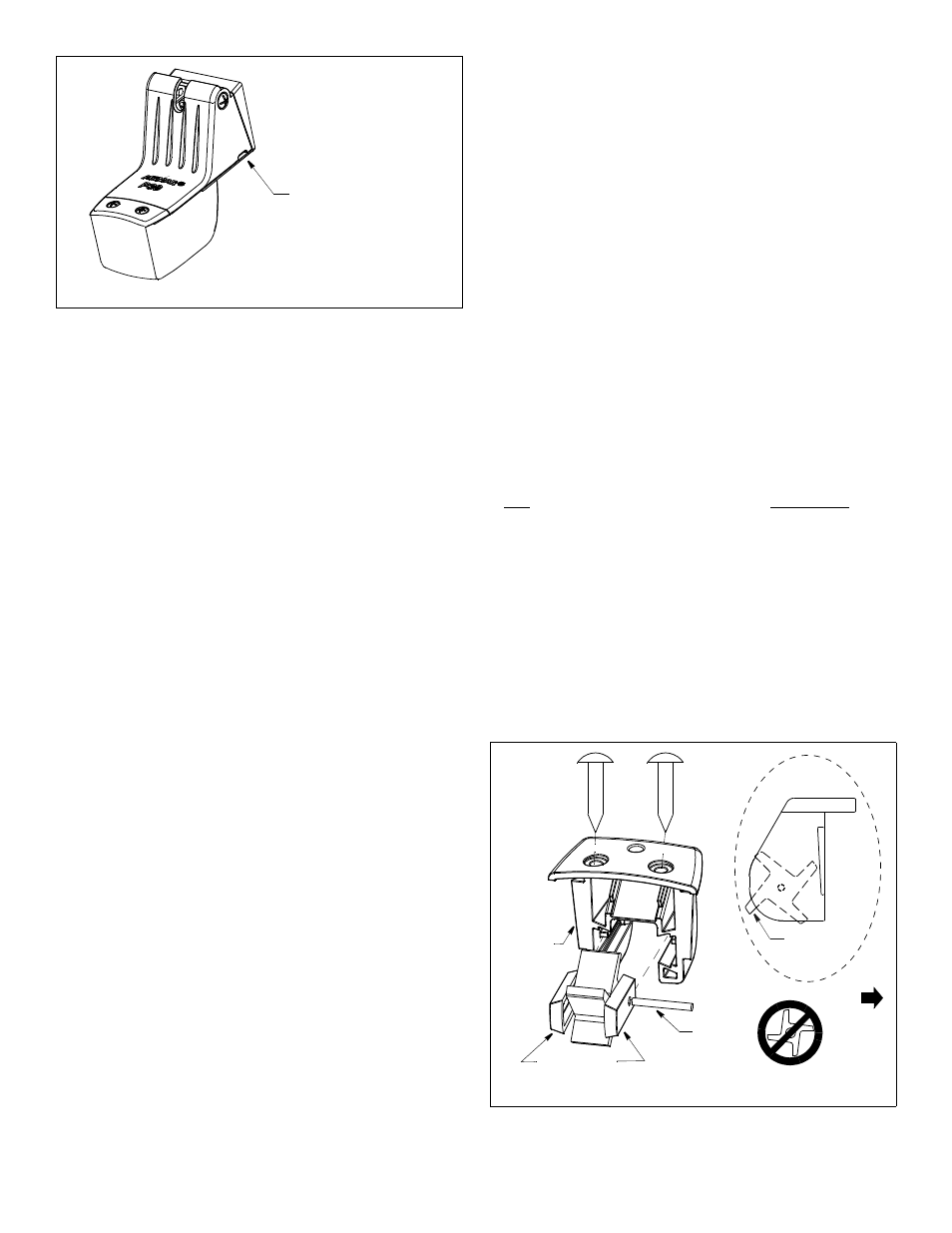
Releasing the transducer
CAUTION: The screwdriver used to release the transducer must
have a blade no more than 3mm or 1/8" wide. Only a small blade
can be inserted far enough into the transducer. A larger
screwdriver will damage the transducer’s housing.
• Before installation—If the transducer is snapped onto the
bracket but not secured to the hull, use this method. Release
the transducer upward by inserting a 3mm or 1/8" blade
screwdriver into one of the slots on the side of the transducer
(see Figure 8). Be sure to insert the screwdriver a full 19mm (3/
4") into the slot. Lift up on the handle of the screwdriver while
lifting up on the transducer.
• After installation—The transducer releases easily when it is
fastened to the hull. Give a sharp blow to the bottom of the
transducer using the palm of the hand. Never strike the speed
sensor.
Anti-fouling Paint
Aquatic growth can accumulate rapidly on the transducer’s
surface reducing performance within weeks. Surfaces exposed to
salt water that do not interlock, must be coated with anti-fouling
paint. Use water-based anti-fouling paint only. Never use ketone-
based paint, since ketones can attack many types of plastic
possibly causing damage to the transducer. Apply paint every 6
months or at the beginning of each boating season.
Cleaning
Clean the transducer with a soft cloth and mild household detergent.
If fouling occurs, use a stiff brush or putty knife to remove the growth
being careful to avoid scratching the transducer’s face. In severe
cases, wet sand the paddlewheel with fine grade wet/dry paper.
Servicing the Speed Sensor
CAUTION: The paddlewheel must be oriented correctly to
measure boat speed.
If the paddlewheel becomes fouled or inoperable, it can be
removed for cleaning. Remove the two screws from the speed
sensor (see Figure 9). Slide the speed sensor upward to remove it
from the transducer. Grasp the paddlewheel and pull to access
the shaft.
After cleaning, slide the paddlewheel onto the shaft. Orient the
short side of the paddlewheel blades as shown on the side view. Fit
the shaft into the holes in the retaining bars. Slide the assembly into
the speed sensor housing. Reattach the speed sensor.
Transducer Replacement & Parts
The information needed to order a replacement transducer is printed
on the cable tag. Do not remove this tag. When ordering, specify the
part number, date, and frequency in kHz. For convenient reference,
record this information on the top of page one.
Replace broken or worn parts immediately. The water-lubricated
paddlewheel bearings have a life of up to 5 years on low-speed
boats [less than 10kn (11MPH)] and 2 years on high-speed
vessels. Some depth/temperature units can be upgraded by
adding a speed sensor.
Part
Part Number
Paddlewheel Kit
33-473-01
Bracket Kit
33-477-01
Speed Sensor Kit
33-478-01
Obtain parts from your instrument manufacturer or marine dealer.
Gemeco
Tel: 803-693-0777
(USA)
Fax: 803-693-0477
email: [email protected]
Airmar EMEA
Tel: +33.(0)2.23.52.06.48
(Europe, Middle East, Africa) Fax: +33.(0)2.23.52.06.49
email: [email protected]
Figure 8. Releasing the transducer
slot (2)
NOTE: Release the transducer
by inserting a 3mm or 1/8" blade
screwdriver in one of the slots.
Lift up on the handle of the
screwdriver while lifting up
on the transducer.
Insert the screwdriver
a full 19mm (3/4") into the slot.
screwdriver
Figure 9. Servicing the speed sensor
side view
retaining bars
short side of
paddlewheel
shaft
blade
speed
ac
tu
al
si
ze
ac
tu
al si
ze
AIRMAR
®
TECHNOLOGY CORPORATION
35 Meadowbrook Drive, Milford, New Hampshire 03055-4613, USA
www.airmar.com
Copyright © 2003 Airmar Technology Corp.
Copyright © 2003 Airmar Technology Corp.
sensor
housing
BOW
before it is secured to the hull