Anti-fouling paint, Mounting location, Installation – Airmar CS4500-650—Ultrasonic Speed User Manual
Page 2: Hole drilling
2
metal housing
safety ring (2)
sealant on flange
ultrasonic insert
safety wire
cap nut
hull nut
washer
hull
retaining pin
Mild household detergent or weak solvent (such as alcohol)
File (installation in a metal hull)
Marine sealant (suitable for below waterline)
Additional washer [for aluminum hull less than 6mm (1/4") thick]
Slip-joint pliers (installing a metal housing)
Grommets (some installations)
Installation in a cored fiberglass hull (see page 3)
Hole saw for hull interior
60mm or 2-3/8"
Fiberglass cloth and resin
or Cylinder, wax, tape, and casting epoxy
Anti-fouling Paint
Aquatic growth can accumulate rapidly on the ultrasonic sensor’s
surface reducing performance within weeks. Surfaces exposed to
salt water must be coated with anti-fouling paint. Use water-based
anti-fouling paint only. Never use ketone-based paint, since
ketones can attack many plastics possibly damaging the sensor.
It is easier to apply anti-fouling paint before installing the sensor,
but allow sufficient drying time. Reapply paint every 6 months or
at the beginning of each boating season. Paint the following
surfaces (see Figure 2):
• Outside wall of the ultrasonic insert below the lower o-ring
• Active face of the ultrasonic insert
• Exterior flange of the housing and valve assembly
• Bore of the valve assembly up 30mm (1-1/4")
• Blanking plug below lowest o-ring including exposed end
Mounting Location
CAUTION: Do not mount near water intake or discharge openings
or behind strakes, fittings, or hull irregularities that will disturb the
water flow.
CAUTION: Never mount the sensor directly ahead of a depth
transducer, since turbulence generated by the housing will
adversely affect the depth transducer’s performance, especially
at high speeds. Mount side-by-side.
CAUTION: Do not mount in line with trailer rollers or bunks that
may damage the sensor.
Turbulence-free water must flow under the ultrasonic sensor at all
speeds. Choose an accessible spot with a minimum of 280mm
(11") of headroom inside the vessel to allow for the height of the
housing, tightening the nuts, and removing the insert.
• Fin keel sailboats—Mount on or near the centerline and
forward of the fin keel 150–300mm (1/2–1').
• Full keel sailboats—Locate amidships and away from the keel
at the point of minimum deadrise.
• Displacement hull powerboats—Locate amidships near the
centerline.
• Planing hull powerboat—Mount well aft to ensure the sensor
is in contact with the water at high speeds.
Installation
Hole Drilling
Cored fiberglass hull—Follow separate instructions on page 3.
1. Drill a 3mm or 1/8" pilot hole from inside the hull. If there is a rib,
strut, or other hull irregularity near the selected mounting
location, drill from the outside.
2. Using the 51mm or 2" hole saw, cut the hole perpendicular to
the hull from outside the hull.
3. Sand and clean the area around the hole, inside and outside, to
ensure that the sealant will adhere properly to the hull. If there is
any petroleum residue inside the hull, remove it with either mild
household detergent or a weak solvent (alcohol) before sanding.
Metal hull—Remove all burrs with a file and sandpaper.
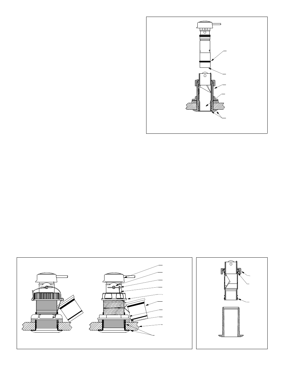
Figure 2. Anti-fouling paint
bore of
valve assembly
exterior flange of housing
and valve assembly
outside wall below
lower o-ring
ultrasonic
up 30mm (1-1/4")
housing
insert
active face
& valve
assembly
housing
Figure 3. Bedding and installing
plastic housing
Figure 4. Assembly
valve
housing
medium
cap nut
o-ring
large
o-ring
assembly
emergency plug
and side wall
Copyright © 2002 - 2011 Airmar Technology Corp.
Copyright © 2002 - 2011 Airmar Technology Corp.
Copyright © 2002 Airmar Technology Corp.