Tools & materials, Mounting location, Anti-fouling paint – Airmar Tilted Element™ Retractable with Valve—DT800: 0°/12°/20° User Manual
Page 2: Installation, Boat types, Hole drilling, Bedding
Tools & Materials
Safety goggles
Dust mask
Electric drill with 10mm (3/8") or larger chuck capacity
Drill bit:
3mm or 1/8"
Hole saw:
51mm or 2"
(plastic or metal housing in non-metal hull)
57mm or 2-1/4"
(stainless steel housing in a metal hull)
Sandpaper
Mild household detergent or weak solvent (such as alcohol)
File (installation in a metal hull)
Marine sealant (suitable for below waterline)
Slip-joint pliers (installing a metal housing)
Grommet(s) (some installations)
Cable ties
Water-based anti-fouling paint (mandatory in salt water)
Installation in a cored fiberglass hull (see page 3):
Hole saw for hull interior:
60mm or 2-3/8"
Fiberglass cloth and resin
or Cylinder, wax, tape, and casting epoxy
Mounting Location
CAUTION: Do not mount in line with or near water intake or
discharge openings or behind strakes, fittings, or hull irregularities
that may disturb the water flow.
CAUTION: Do not mount the sensor where the boat may be
supported during trailering, launching, hauling, or storage to avoid
damaging the transducer’s face.
• The water flowing under the hull must be smooth with a
minimum of bubbles and turbulence (especially at high speeds).
• The transducer must be continuously immersed in water.
• The transducer beam must be unobstructed by the keel or
propeller shaft(s).
• Choose a location away from interference caused by power and
radiation sources such as: the propeller(s) and shaft(s), other
machinery, other echosounders, and other cables. The lower
the noise level, the higher the echosounder gain setting that
can be used.
• Choose an accessible spot inside the vessel with adequate
headroom for the height of the housing, tightening the nuts, and
removing the insert. Allow a minimum of 280mm (11").
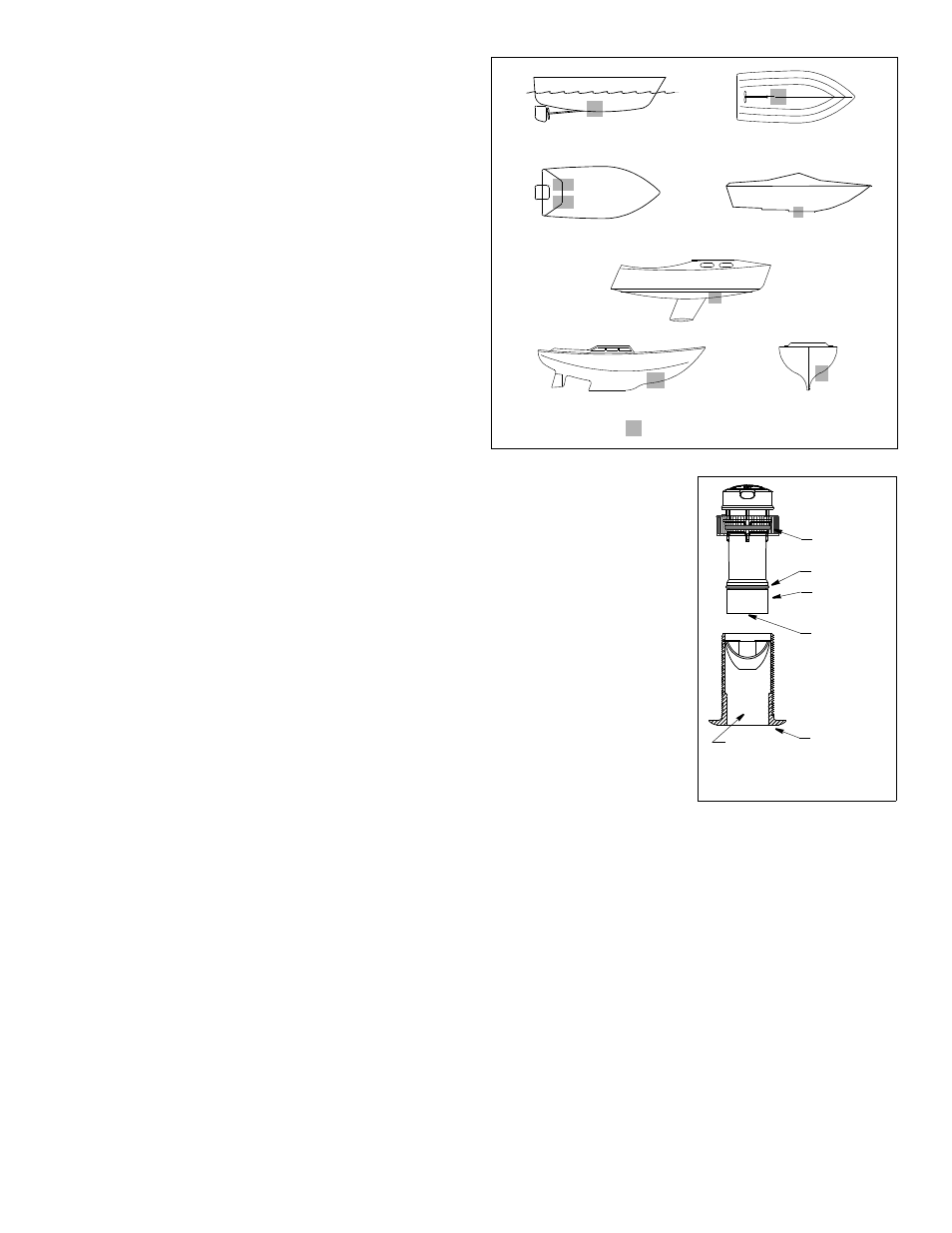
Boat Types
(see Figure 3)
• Displacement hull powerboats—Locate amidships near the
centerline. The starboard side of the hull where the propeller
blades are moving downward is preferred.
• Planing hull powerboats—Mount well aft, on or near the
centerline, and well inboard of the first set of lifting strakes to
ensure that the transducer will be in contact with the water at
high speeds. The starboard side of the hull where the propeller
blades are moving downward is preferred.
Outboard and I/O—Mount just forward of the engine(s).
Inboard—Mount well ahead of the propeller(s) and shaft(s).
Stepped hull—Mount just ahead of the first step.
Boat capable of speeds above 25kn (29MPH)—Review the
installation location and operating results of similar boats before
proceeding.
• Fin keel sailboats—Mount on or near the centerline and
forward of the fin keel 300–600mm (1–2').
• Full keel sailboats—Locate amidships and away from the keel.
Anti-fouling Paint
Surfaces exposed to salt water must be coated with anti-fouling
paint. Use water-based anti-fouling paint only. Never use ketone-
based paint, since ketones can attack many plastics possibly
damaging the transducer.
It is easier to apply paint before
installation, but allow sufficient
drying time. Reapply paint every
6 months or at the beginning of
each boating season. Paint the
following surfaces (see Figure 4):
• Outside wall of the insert
below the lower O-ring
• Exposed end of the insert
• Exterior flange of the housing
• Bore of the housing up 30mm
(1-1/4")
• Blanking plug below the lower
O-ring including the exposed
end
Installation
Hole Drilling
Cored fiberglass hull—Follow separate instructions on page 3.
1. Drill a 3mm or 1/8" pilot hole from inside the hull. If there is a rib,
strut or other hull irregularity near the selected mounting location,
drill from the outside.
2. Using the appropriate size hole saw, cut a hole perpendicular to
the hull from outside the boat.
3. Sand and clean the area around the hole, inside and outside, to
ensure that the sealant will adhere properly to the hull. If there is
any petroleum residue inside the hull, remove it with either mild
household detergent or a weak solvent (alcohol) before sanding.
Metal hull—Remove all burrs with a file and sandpaper.
Bedding
CAUTION: Be sure the surfaces to be bedded are clean and dry.
Apply a 2mm (1/16") thick layer of marine sealant around the
flange of the housing that will contact the hull and up the sidewall
of the housing (see Figure 5). The sealant must extend 6mm
(1/4") higher than the combined thickness of the hull, the washer,
and the hull nut. This will ensure there is sealant in the threads to
seal the hull and to hold the hull nut securely in place.
2
planing hulls
Figure 3.
full keel sailboats
large displacement hulls
small displacement hulls
fin keel sailboats
Best location for transducer
Copyright © 2005 Airmar Technology Corp.
stepped hull
outboard and I/O
Figure 4. Anti-fouling paint
outside wall
bore up
exterior
O-ring
below lower
30mm (1-1/4")
of flange
insert
housing
exposed end
Copyright © 2006 - 2011 Airmar Technology Corp.
yellow O-ring
(under cap nut)
O-ring