2 led indicators – Airlink AME001 User Manual
Page 7
External Modem User's Manual
4
Step 5:
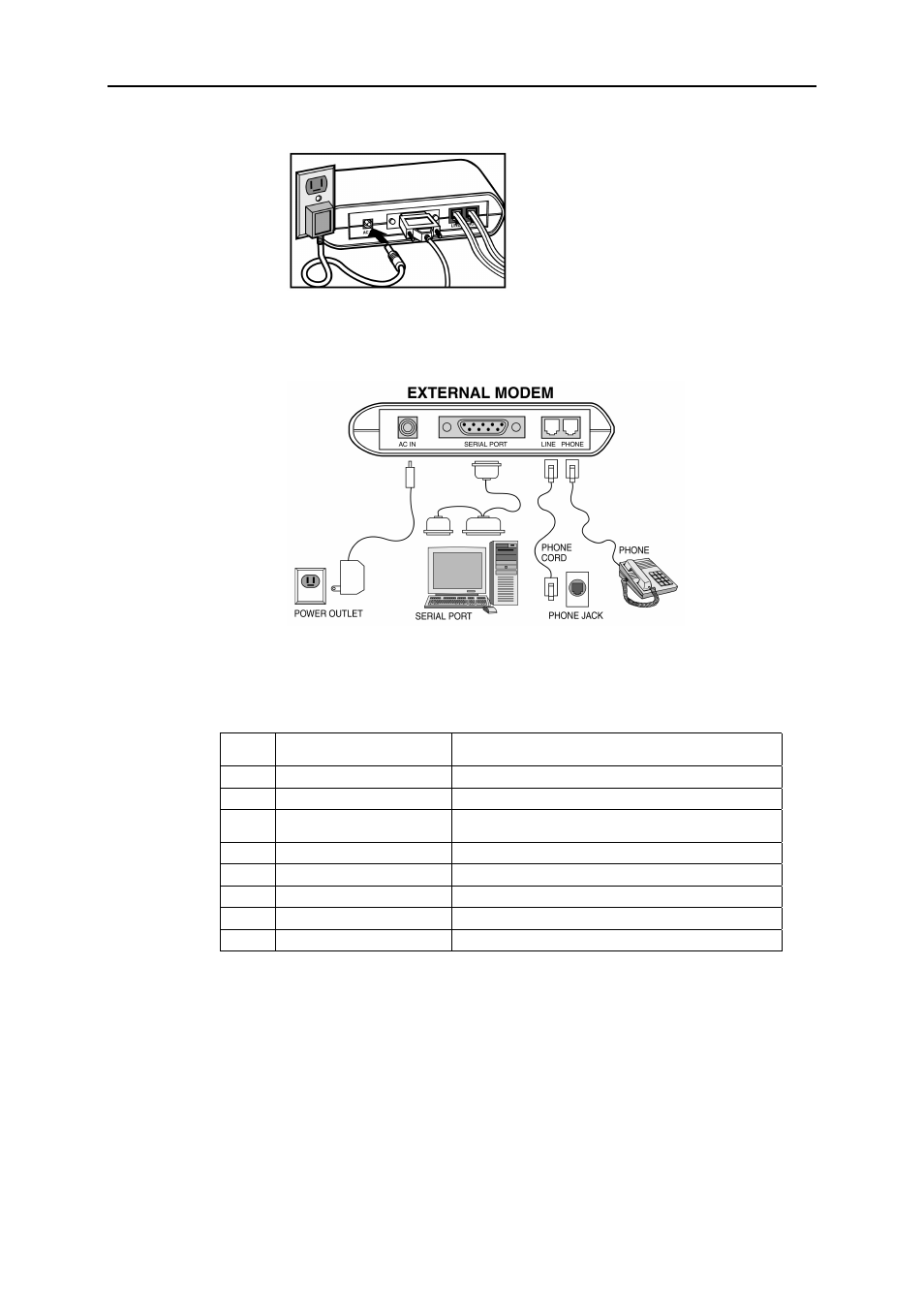
Plug the AC adapter into the modem’s AC IN jack, and plug the other end into an
electrical outlet.
Step 6:
When connection is finished, power on your modem before you power on your PC.
The diagram below illustrates the typical external modem connection:
2.2 LED Indicators
After hardware installation, turn on the modem and then your computer. The PWR, HS, and
MR LEDs should illuminate. The description of the LED indicators on the front panel are
listed below (from left to right) :
MR
Modem Ready/ Self-testing
On: Power on
Flash: Self-testing/ In diagnostic mode
HS
High Speed Speeds
On: Operating speed at 24000bps or higher
CD
Carrier Detect
On: Receiving a data carrier signal from remote modem
OH
Off Hook
On: Modem off hook
Off: Modem on hook
SD
Send Data
Flash: Transferring data from the modem
RD
Receive Data
Flash: Receiving data to the modem
TR
Terminal Ready
On: Modem is on (unless setup by AT commands)
AA
Auto-answer
On: Set up to answer incoming calls
PWR Power
On: power on