Installation guide – ACTi Outdoor Hemispheric / Fisheye Dome on Straight Wall with Tilted Mount User Manual
Page 19
Installation Guide
To connect output devices (DO), map the pins to one of the pin combinations below:
Device
Pin
Mapping Instructions
Digital Output 1
(DO1)
2
12V
Connect the wires of the first output device to
12V
(Pin 2) and
DO1
(Pin 4).
4
DO1
Digital Output 2
(DO2)
6
12V
Connect the wires of the second output device to
12V
(Pin 6) and
DO2
(Pin 8).
8
DO2
The table below shows the DI/DO connection specifications:
Device
DI
Connection design
TTL - compatible logic levels
Voltage
To trigger (low)
Logic level 0: 0V ~ 0.4V
Normal (high)
Logic level 1: 3.1V ~ 30V
Current
10mA ~ 100mA
DO
Connection design
Transistor (Open Collector)
Voltage & Current
< 24V DC, < 100mA
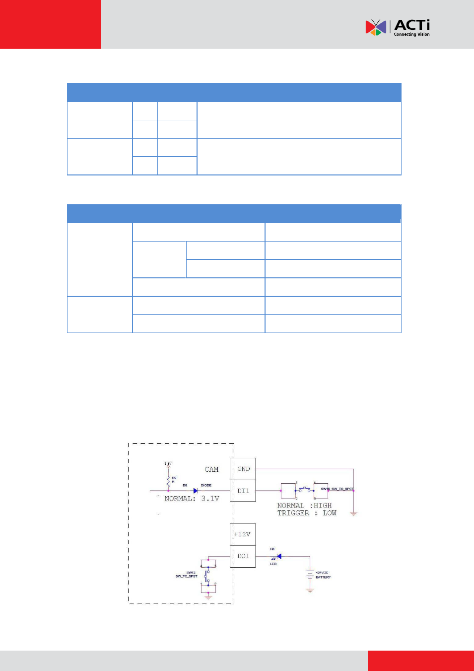
Typical Connection
Based on these specifications, if the DI device has a voltage of 0V ~ 30V or the DO device has a
voltage of < 24V (<100mA), then the camera can supply internal power to these devices and
there is no need to connect the DI/DO device to an external power source.
In this case, wire connection to Pins 1 to 4. Use the
GND
and
DI1
pins to connect a DI device and
use the
12V
and
DO1
pins to connect a DO device. See wiring scheme below:
Consequently, to connect a second DI or DO device, wire the connection to Pins 5 to 8.