Westermo RM-115S User Manual
Page 7
115S Serial I/O Module
User Manual
man_115S_1.14.docx
Page 7
1.1 Module types and features
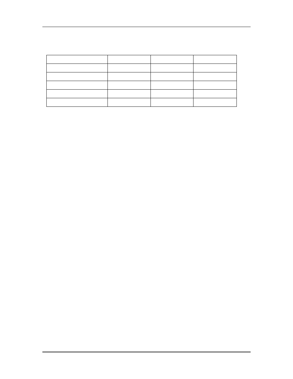
The module types and I/O are summarised in Table 1-1.
115S
-11
-12
-13
Digital inputs/outputs
16
8
8
Pulse outputs
8
8
8
Pulse inputs
4
-
-
Analog inputs
-
8
-
Analog outputs
-
-
8
Table 1-1: Summary of 115S module types and I/O.
1.1.1 Digital inputs / outputs
Each digital I/O channel on the 115S modules can act as either an input or an output. The
input/output direction does not need to be user configured.
Digital inputs are suitable for voltage-free contacts, or NPN-transistor switch devices.
Digital outputs are open-collector transistor outputs, able to switch loads up to 30VDC,
200mA.
If you have wired an input/output channel as an input, it is recommended that you do not
write values to it as an output. No electrical damage will occur if you attempt to use a
channel wired as an input as an output, or vice-versa, however the I/O system will not
operate correctly.
We recommend that the required digital inputs be assigned consecutively from channel 1.
Then use the remaining channels as digital outputs.
1.1.2 Pulsed outputs
The first eight digital channels on each 115S module can be used as pulse outputs. The
maximum output frequency is 50Hz.
A pulse output on the 115S will output the number of pulses equal to the register value
sent by the master. When the master sends a new register value, the 115S will output
additional pulses until the output count is the same as the new value.
Three register values are associated with creating each pulsed output:
• The Count keeps a tally of how many pulses have been output - this is a 16-bit
register and overflows to 0.
• The Target is set by the master, and is the trigger for pulses to be created. The
digital channel outputs pulses until the Count value reaches the Target value. If
the Target register is set to 0, the pulses stop and the Count register is cleared.