Expansion board installation & wiring, Technical guide mua ii controller 9, Jumper settings – WattMaster MUA II User Manual
Page 9: Figure 6: expansion board jumper settings, 4 relay output expansion board
Technical Guide
MUA II Controller
9
Jumpers
Under
Expansion
Board To Be
Set As Shown
Common
N.O. Contact #6 - Configurable
N.O. Contact #7 - Configurable
N.O. Contact #8 - Configurable
N.O. Contact #9 - Configurable
4 Relay Output Expansion Board
UL5A250V
AC
G5L-114P
-PS
OMRON
CONTACT
:
24VDC
UL5A250V
AC
G5L-114P
-PS
OMRON
CONTACT
:
24VDC
UL5A250V
AC
G5L-114P
-PS
OMRON
CONTACT
:
24VDC
UL5A250V
AC
G5L-114P
-PS
OMRON
CONTACT
:
24VDC
K3
K2
4RLY IO BD.
V4
K4
YS101790
TB1
V1
K1
K3
U2
K4
RN1
PCF8574P
U1
T L
HA
AN
I D
ULN2803A/
K2
K1
74HC04N
PHILIPS
P1
CX2
CX1
Relays 6-9
Relays 10-13
Relays 14-17 Relays 18-21
Address Jumpers
Relay Outputs - 6 Through 21
Expansion Board Installation & Wiring
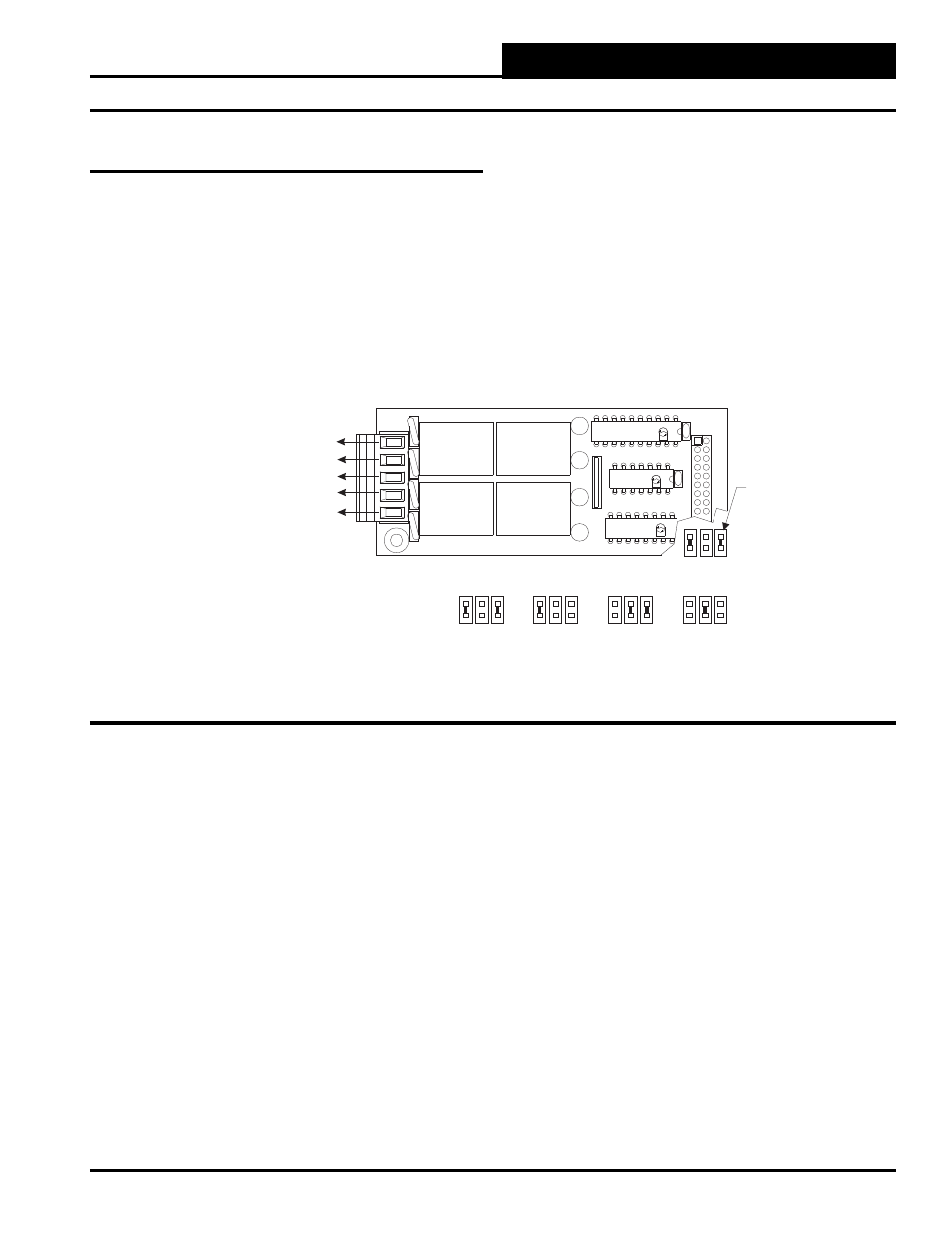
Figure 6: Expansion Board Jumper Settings
Jumper Settings
The expansion boards are connected to the MUA II Controller with
a modular cable. Up to 2 Expansion Base Boards can be populated
with expansion boards to provide additional inputs and outputs. The
expansion boards can be placed on the expansion base board in any
order; however, the jumpers on the Expansion Base Board must be set
correctly for proper operation. See Figure 6 for correct jumper settings
and jumper locations.