Wiring details, Mua ii controller technical guide 14, Outside air humidity sensor – WattMaster MUA II User Manual
Page 14
MUA II Controller
Technical Guide
14
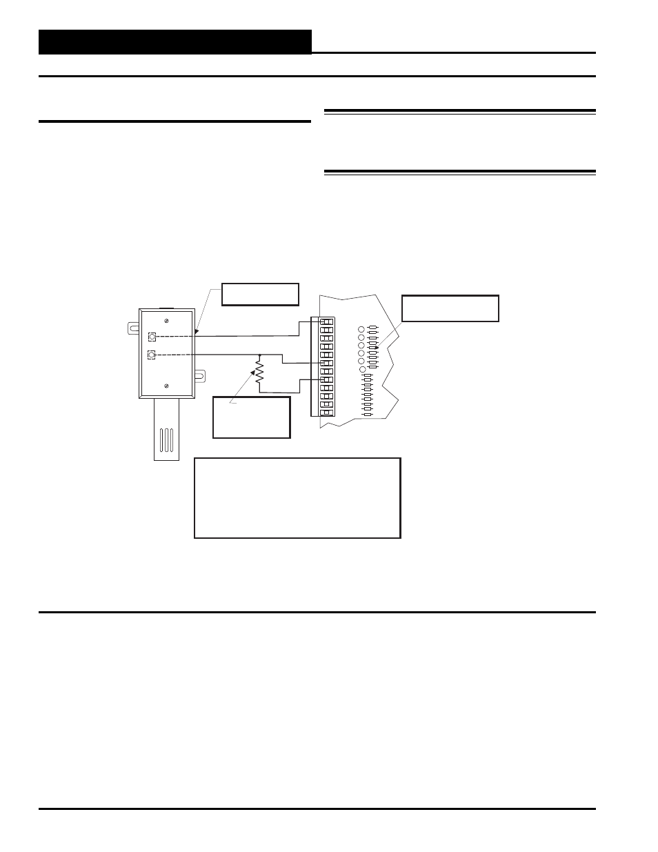
Figure 12: Humidity
Sensor Wiring
GND
INPUTS
GND
AOUT1
AOUT2
GND
+VDC
AIN1
AIN2
AIN3
AIN4
AIN5
AIN7
Outdoor
Air Humidity
Sensor - 4-20mA
Seal All Conduit Fittings
With Silicone Sealant.
MUA II Controller Board
250 Ohm
Resistor
(Shipped With Sensor)
To be Installed Between
AIN5 and GND
The Pull-up Resistor (PU5)
Must Be Removed
When Using A 4-20ma Device
If You Are Using The Standard Factory Supplied Humidity Sensor, It
Has Terminals Labeled “H+ (T1)” And “H- (T4)”. Terminal “H+ (T1)” Is
The Voltage Input And Should Be Connected To The Terminal Labeled
+VDC On The VAV/CAV Controller. Terminal “H- (T4)” Is The 4-20 Ma
Output Signal And Should Be Connected To The Terminal Labeled AIN
5 On The VAV/CAV Controller.
If A Sensor Other Than The One Supplied By The
Factory Is Used, Refer To The Wiring Instructions Shipped With The
Sensor.
A Factory Supplied 250 Ohm Resistor
Should Be Connected Between AIN 5 And A Ground Terminal On The
VAV/CAV Controller.
H-(T4)
H+(T1)
Outside Air Humidity Sensor
If you want to install a humidity sensor onto the MUA II Controller, it
is important that you follow these instructions. There are 2 terminals
labeled “H+” and “H-”. Terminal “H+” will connect to the connection
labeled “+VDC” on the analog input block. See Figure 12. Terminal
“H-” connects to the connection labeled “AIN 5” on the analog input
block. Also, the resistor labeled “PU5” needs to be removed. Lastly, a
supplied 250 Ohm, ¼ Watt, 1% resistor needs to be installed between
“AIN 5” and “GND”. See Figure 12 for detailed wiring.
Warning: It is very important to be certain that all wiring is
correct as shown in the wiring diagram below.
Failure to observe the correct polarity will result in
damage to the Humidity Sensor or controller.
Wiring Details