Start-up & commissioning, Mua ii controller technical guide 16, Controller addressing – WattMaster MUA II User Manual
Page 16: Power wiring
MUA II Controller
Technical Guide
16
Start-up & Commissioning
In order to have a trouble free start-up, it is important to follow a few
simple procedures. Before applying power for the fi rst time, it is very
important to correctly address the controller and run through a few
simple checks.
Controller Addressing
All MUA II Controllers are equipped with address switches. If the MUA
II Controller is to operate as a stand-alone system (not connected to any
other controllers), the controller address switch should be set for address
1. When using the Modular Service Tool or System Manager to program
and confi gure the MUA II Controller, you would enter this address to
communicate with the controller. When the system is to be connected to
other HVAC unit controllers on a communication loop, each controllers
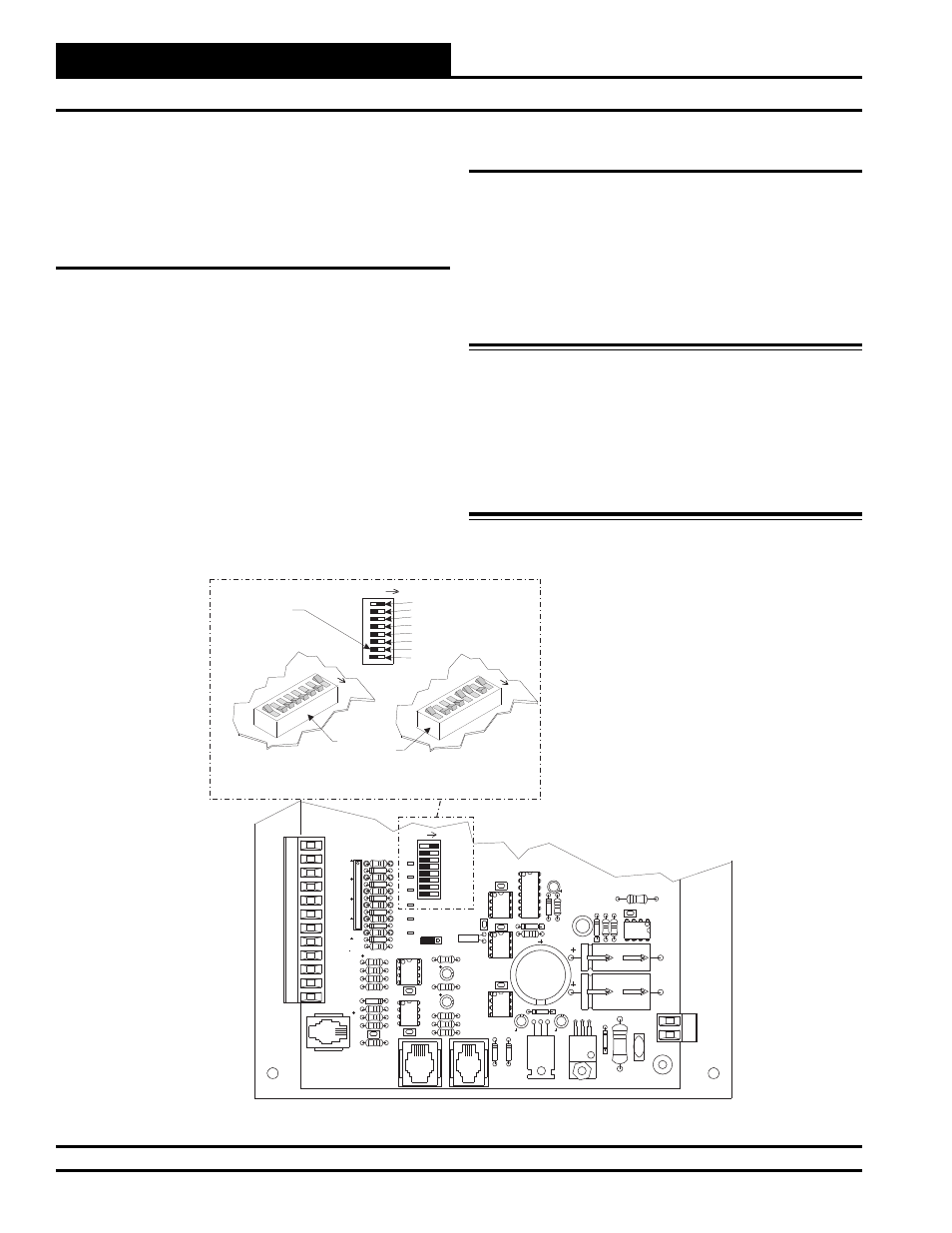
address switch must be set with a unique address between 1 and 59. See
Figure 15 for address switch setting information.
4
NETWORK
TOKEN
16
32
8
SW1
ADD
2
1
ADDRESS
V6
POWER
GND
24VAC
L1
D16
R6
C9
SC1
R1
1
U1
1
D13
C16
VR2
TB4
R27
C13
R10
VR1
C19
C18
R7
D10
R13
D12
C7
CX10
U10
CX12
U12
U14
CX14
PJ3
PJ2
PJ1
EXPANSION
PRESSURE
SENSOR
C17
D15
R26
C20
R25
R24
R22
U15
CX13
U13
C15
R19
R15
C14
D18
D17
PU1
PU2
PU3
PU4
PU5
PU7
D6
D7
D8
D9
D11
D14
C12
C10
0-5
VDC
0-1
VDC
JP1
C1
1
X2
GND
TB3
INPUTS
GND
GND
+VDC
AIN1
AIN2
AIN3
AIN4
AIN5
AOUT1
AOUT2
AIN7
RN5
D19
CX15
16
32
TOKEN
NETWORK
8
4
2
1
Address Switch Shown Is
Set For Address 1
Address Switch Shown Is
Set For Address 13
Controller
Address Switch
This Switch Should Be
In The OFF Position
As Shown
Note:
The Power To The Controller Must Be Removed And
Reconnected After Changing The Address Switch Settings
Caution
Disconnect All Communication Loop Wiring From The
Controller Before Removing Power From The Controller.
Reconnect Power And Then Reconnect Communication Loop
Wiring.
ADDRESS
ADD
ADDRESS
ADD
ADDRESS
ADD
The Address For Each Controller
Must Be Unique To The Other Controllers
On The Local Loop And Be Between 1 and 59
Figure 15: MUA II Controller Address Switch Setting
Power Wiring
One of the most important checks to make before powering up the system
for the fi rst time, is to confi rm proper voltage and transformer sizing for
the controller. Each MUA II Controller requires 10 VA of power delivered
to it at 24 VAC. Each 2-slot expansion board requires 5 VA at 24 VAC
and each 4-slot expansion board requires 10 VA at 24 VAC. You may
use separate transformers for each device (preferred) or power several
devices from a common transformer. If several devices are to be powered
from a single transformer, correct polarity must be followed.
Warning: Observe Polarity! All boards must be wired with
GND-to-GND and 24 VAC-to-24 VAC. Failure to
o b s e r v e p o l a r i t y w i l l r e s u l t i n d a m a g e t o
one or more of the boards. Expansion Boards must be
wired in such a way that power to both the expansion
boards and the controller are always powered together.
Loss of power to the expansion board will cause the
controller to become inoperative until power is
restored to the expansion board.