3 installation, Installation, Instruction handbook – Watson-Marlow PD12 IHS User Manual
Page 6
INSTRUCTION HANDBOOK
PD12IHS / PD12IDH
PD12IHS_PD12IDH IH EN 74-115-181 v2.00.doc
Version: 2.00
Page 6 of 19
Other:
Weight:
13 kg
Motor:
High Torque Step Motor MST341B02
PD12 Power consumption:
max 150 Watt
Mains:
110/230 VAC earthed, 50/60 Hz
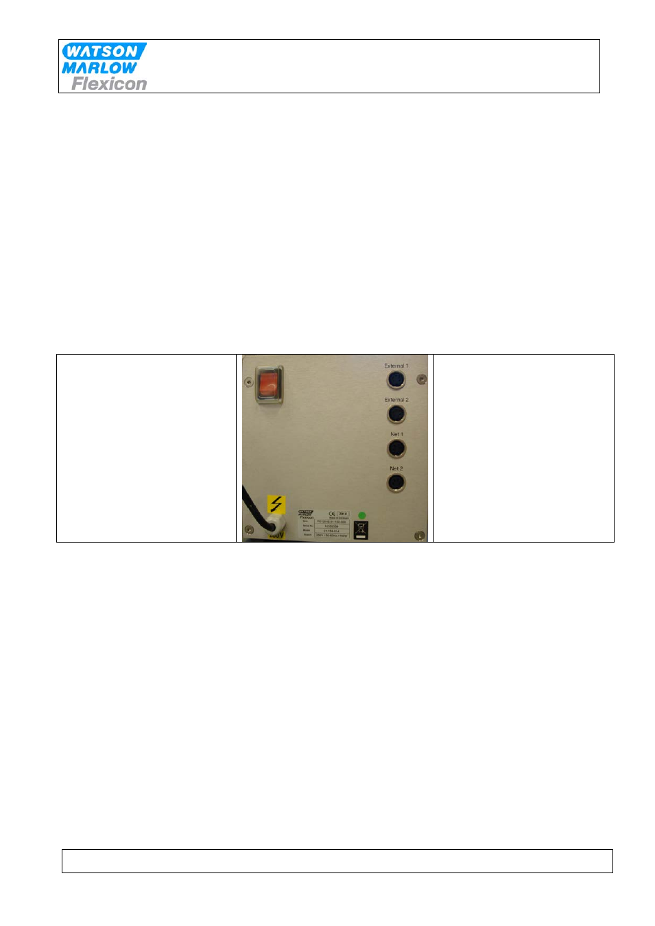
3 Installation
PD12 must be placed on a stable bedplate. All electrical connections are on its rear.
1
2
3
Fig. 4 - Connections
The cable with plug (1) is connected to an earthed switch.
The communication cable from MC12 (type 3) comes fitted with two 4-pin DIN plugs. One is
connected to the "net 1" socket (2) on the PD12, and the other plug is connected to the "net" socket
on MC12.
The terminator supplied with MC12 (4-pin blind DIN plug) is connected to the "net 2" (3) socket on
PD12.
Should the system be operating more than one PD12, the "net 2" socket (3) is to be connected to the
"net 1" socket (2) on the next PD12 by a communication cable (type 3). The terminator is connected
to the last PD12 on the line.
PD12 is now ready to be switched on and to be programmed from the MC12.
If the PD12 is one of several filling stations in a system, none of the stations may have the same
address and it must therefore be changed.