Watson-Marlow 605Di User Manual
Page 9
8
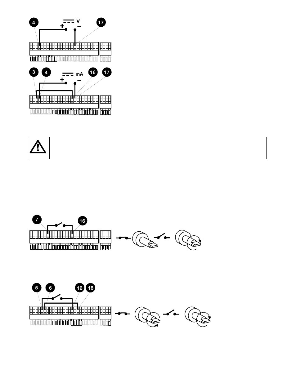
For voltage modes a stable, variable DC voltage source can be used in
conjunction with a DC voltmeter, (max 30V DC). (Refer to the 25 pin cage
clamp connector wiring detail as an example of control circuitry) Circuit
impedance 100k
Ω. Polarity set for non-inverted response. Reverse polarity for
inverted response.
For current modes the same DC source can be used in conjunction with a DC
milliampere meter, (maximum 32mA). (See 25 pin cage clamp connector
detail). Circuit impedance 250
Ω. Polarity set for non-inverted response.
Reverse polarity for inverted response.
Trim - This function will match the pumps signal conditioner to the analogue process control signal if they do not fully coincide.
The user will be asked to apply zero, 20% and the maximum voltage or current that is required to be the control signal. Press enter
after adjusting the process signal to each input level.
Never apply mains voltage across pins on the 25 pin cage clamp connector. Up to 5V TTL may be applied to
pins 7 and 5, but do not apply voltage across any other pins. Failure to heed this warning could cause
permanent damage not covered by warranty. Do not use the mains power switch to control the pump for a
high repetition of stop starts. The auto-control facility should be used.
Remote control
Pause dose
This function will pause a dose on for as long as a remote switch remains closed then allows the dose to continue when the switch
is opened. Under Manual mode it will also act as a remote stop/start. Connect remote switch as in the Stop/Start diagram. Open to
run pump, close to pause or stop pump.
Stop/Start
Connect remote switch between pins 7 and 16 of the 25 pin cage clamp connector. A TTL compatible logic input (Low 0V, High 5V)
may be applied to pin 7. Low input stops the pump, high input runs the pump. With no connection, the pump will default to running.
Direction
Connect remote switch between pins 5 and 16 and disable the front panel reversing control by linking pins 6 and 18 of the 25 pin
cage clamp connector. Open switch for clockwise rotation, close for counter-clockwise. Alternatively a TTL compatible logic input
(Low 0V, High 5V) may be applied to pin 5. Low input will run the pump in a counter-clockwise direction, High input in a clockwise
rotation. No connection; the pump will default to clockwise rotation.
Speed
A remote potentiometer with a nominal 1k
Ω and 2kΩ minimum 0.25W should be wired as shown. When using a remote
potentiometer, do not apply a voltage/current control input signal at the same time. The pump must be calibrated for 0-12V
analogue signal control under the "PROGRAM" option of Signal in Setup. Alternatively, the potentiometer may be used for the
calibration procedure, instead of using the minimum and maximum analogue process signal settings, if it is set to its minimum and
maximum positions.