Seal system - disassembly and assembly, cont – Watson-Marlow MR-Series User Manual
Page 15
Revision 1.4 / August 2013
Visit our website at
www.masosine.com
15
Seal System - Disassembly and Assembly, cont.
2. Place the seal housing in a press with the removal holes at the top of the housing. This side of the
seal housing will face into the wet end of the pump. Insert one support ring, item 520, into the seal
housing such that the flat surface of the ring rests on the step in the housing. This will not require
a press.
3. Press one of the lip seals, item 510, into the seal housing with the lip side of the seal facing out of
the housing using the press plug diameter listed in Table 2 for your specific pump model. Press
the seal in until it fits securely over the support ring.
Table 2 – Lip Seal, Press (INTO) Plug Diameters
MR-120
=
1-9/16”
or
39.6 mm
MR-125
=
2-7/32”
or
56.3 mm
MR-130
=
2-5/8”
or
66.6 mm
MR-135
=
3”
or
76.2 mm
MR-150
=
3-29/32”
or
99.2 mm
NOTE: Apply even pressure to the lip seal to prevent it from lodging sideways in the housing
.
4. Insert the other support ring, item 520, into the seal housing such that the flat surface of the ring
rests on the lip seal. This will not require a press.
5. Press the second lip seal, item 510, into the seal housing with the lip side of the seal facing out of
the housing using the press plug diameter listed in Table 2 for your specific pump model. Press
the seal in until it fits securely over the support ring. NOTE: Apply even pressure to the lip seal
to prevent it from lodging sideways in the housing
6. Turn the seal housing over such that the removal holes in the housing are at the bottom. This side
of the seal housing will face the power end of the pump. Press the third lip seal, item 510, into the
seal housing with the lip side of the seal facing out of the housing. Press the lip seal in until the flat
side of the seal rests on the step in the seal housing. NOTE: Apply even pressure to the lip seal
to prevent it from lodging sideways in the housing
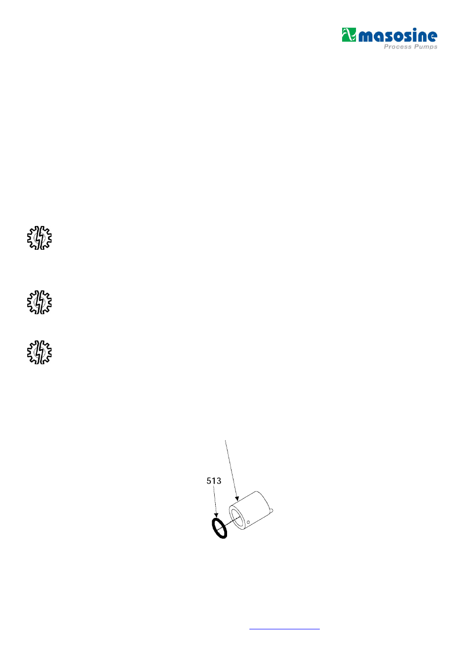
B. O-Ring Seal
Reference the isometric drawing in
Figure 5 – O-Ring Seal
for parts identification while following the o-ring
seal disassembly and assembly steps.
Figure 5 – O-Ring Seal Disassembly / Assembly
620