Watson-Marlow MR-Series User Manual
Page 11
Revision 1.4 / August 2013
Visit our website at
www.masosine.com
11
Wet End Disassembly, cont.
10. The front cover o-ring, item 430, can then be placed into the groove on the front of the pump
housing. Applying a food grade lubricant to the o-ring will keep it from slipping out of the groove.
11. If the front support, item 370, is stainless steel, replace the dynamic face o-ring, item 515, by
placing it into the groove at the end of the front support. Apply a food grade lubricant to the o-ring
before installing. Place the front support into the bore in the front cover, item 400, with the slots
being installed first
12. Place the front cover and front support assembly onto the front of the pump housing by lining up
the front cover studs, item 450, with the corresponding holes in the cover. Front cover pins, item
420, have been placed on the outer diameter of the front cover to facilitate this.
13. Install the five wing nuts, item 441, by hand tightening them onto the front cover studs. The wing
nuts may be further tightened with a soft-headed hammer. NOTE: If the front cover does not seat
properly against the pump housing face, remove the cover and examine the internal components
checking for proper alignment.
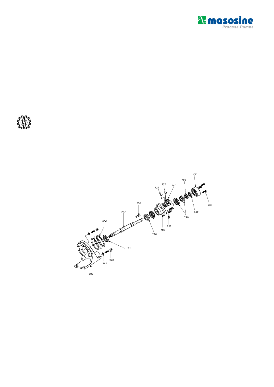
Power End Disassembly
Reference the isometric drawing below for parts identification while following the power end
disassembly an assembly steps.
1. Before beginning the power end disassembly, follow steps 1 through 11 in the wet end
disassembly section of this manual.
2. Drain the oil from the bearing housing, item 700, by removing the oil drain plug, item 737, located
on the bottom of the bearing housing.