Figure 7-3. mounting screws, Figure 7-3, Mounting screws -4 – Visara 1330-X02 User Manual
Page 118: Maintaining the 1330
7-4
701333-004
Maintaining the 1330
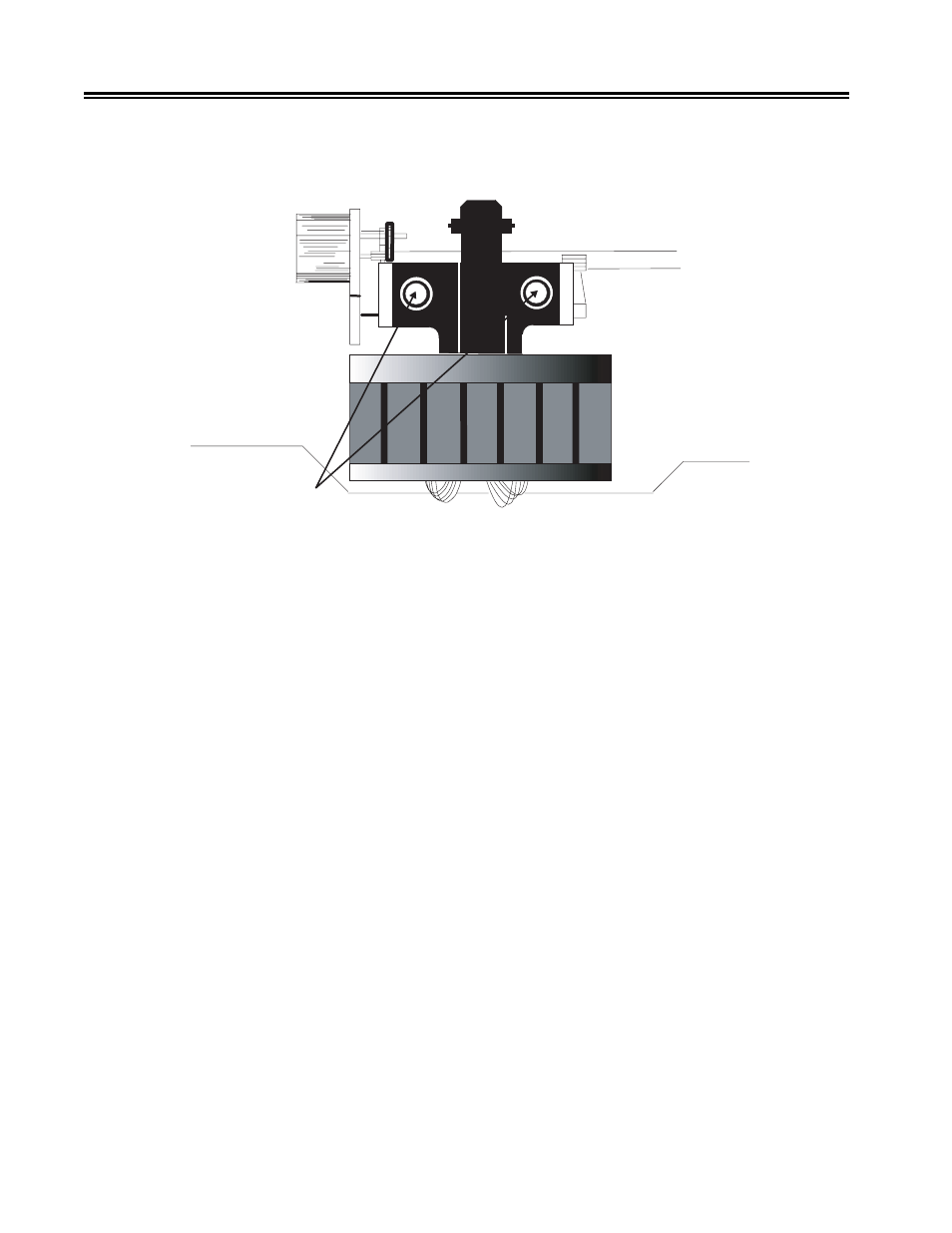
11. Remove the mounting screws on each side of the print head with the hex key provided
with the replacement print head. See Figure 7-3. Remove the print head by carefully
pulling it straight up.
Mounting Screws
Figure 7-3. Mounting Screws
12. Refer to the label on the print head to determine the style of the replacement print
head you are installing (style 1 or style 2).
13. To install the new print head, reverse the print head removal procedure.
14. Install a new tie-wrap to secure the print head wire cable bundle against the hook
area on the carriage assembly. (See Figure 7-4.)
15. Cut and remove the excess from the tie-wrap after assembly.
16. Referring to Figure 7-4, reinstall the connector(s). Make sure that the Ribbon Shifter
Connector cable passes between the two print head cables, so that it will not interfere
with printer operation.
17. Replace the cable, placing the white strip on the cable under the restraining bar.
Snap the bar down.
18. Plug the 1330 into the AC outlet and power on the unit.
19. Press the Stop key, then the Option key.
20. Select Option 404.
21. Enter the number of the print head style you have installed (1 or 2). The status
window display will show your selection.