Boot mode, Table 2-n boot mode, Configuration switch s3 – Verilink PRISM 4001 (34-00244) Product Manual User Manual
Page 14: Figure 2-4 switch s3, Nms rate, Table 2-o nms rate, Supv port rate, Table 2-p supv rate, Dial backup, Table 2-q dial backup
2-4 Installation
PRISM 4001
B
OOT
M
ODE
Positions S2-7 and S2-8 select the startup boot configura-
tion method as shown in Table 2-N.
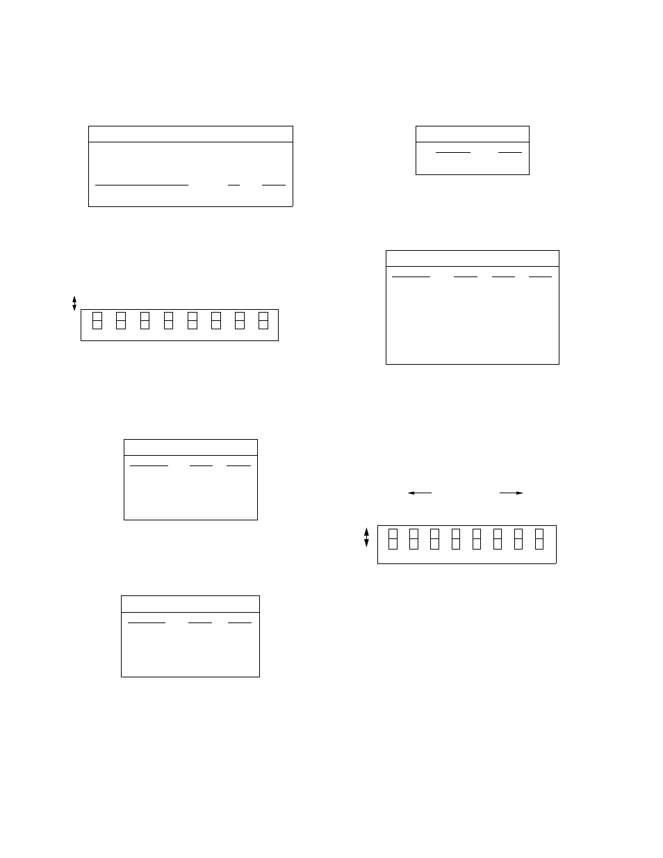
Configuration Switch S3
Switch S3 (Figure 2-4) sets the configuration parameters
listed in the following paragraphs.
NMS R
ATE
Positions S3-1 and S3-2 set the bit rate for the network
management system as shown in Table 2-O.
SUPV P
ORT
R
ATE
Positions S3-3 and S3-4 set the supervisory port rate as
shown in Table 2- P.
D
IAL
B
ACKUP
Position S3-5 can enable the unit’s dial backup feature as
shown in Table 2-Q.
DBU R
ATE
Positions S3-6 through S3-8 set the DBU port rate as shown
in Table 2-R.
Address Switch S4
Switch S4 sets the unit address. When using the 4001 with a
8100A Site Controller, each element in a group must have a
unique unit address. As many as 50 units (with addresses from
1 to 50) can exist in a group. If the unit is not connected to a
site controller, the NMS unit address should be left at the fac-
tory default setting of 1 where Position 1 is Up and all other
positions are Down (see Figure 2-5).
Switch S4 has eight positions used to create an 8-bit binary
code for an address in the range of 1 to 50. Switch position S4-
1is the least significant bit (LSB) and S4-8 is the most signifi-
cant bit (MSB). If a switch is down, its value is 0. If up, its
value is that of the upper location. the values are additive. For
example, to set a unit address to 5, position S4-3 (binary value
is 4) and position S4-1 (binary value is 1 would be set Up for a
unit address of 5 (4+1). All other positions would be set Down.
Interface Switches S5 and S6
Switches S5 and S6 are slide switches that set the unit to
either RS-232 or V.35. Both switches must be set to the
same selection (that is, RS-232 or V.35).
Table 2 -N Boot Mode
Power-up Mode
S2-7
S2-8
Boot from SAVED
Down
Down
Boot from DEFAULT
Down
Up
Boot from SWITCHED
Up
Down
Boot from CONTROLLER
Up
Up
Table 2-O NMS Rate
NMS Rate
S3-1
S3-2
19.2 kbps
Down
Down
1.2 kbps
Down
Up
2.4 kbps
Up
Down
9.6 kbps
Up
Up
Table 2-P SUPV Rate
SUPV Rate
S3-3
S3-4
19.2 kbps
Down
Down
1.2 kbps
Down
Up
2.4 kbps
Up
Down
9.6 kbps
Up
Up
7
6
5
4
3
2
1
8
NM
S
NM
S
SU
P
V
DB
U
DB
U
Rate
Rate
Rate
Rate
DB
U
Rate
Rate
SU
P
V
Rate
Switch
S3
DB
U
En
ab
le
Figure 2 -4 Switch S3
Do
wn
Up
Table 2-Q Dial Backup
Dial Backup
S3-5
Disabled
Down
Enabled
Up
Table 2-R DBU Rate
DBU Rate
S3-6
S3-7
S3-8
57.6 kbps
Down
Down
Down
2.4 kbps
Down
Down
Up
4.8 kbps
Down
Up
Down
9.6 kbps
Down
Up
Up
19.2 kbps
Up
Down
Down
38.4 kbps
Up
Down
Up
7
6
5
4
3
2
1
8
LSB
MSB
Binary values
D
o
w
n
U
p
1
2
4
8
16
32
64 128
0
0
0
0
0
0
0
0
Switch
S4
Figure 2 -5 Switch S4