Front panel interface, Power, Test – Verilink PRISM 3301 (34-00239.5) Product Manual User Manual
Page 19: Dte clock loss, Power test dte clock loss, Front panel interface - thi, Ront, Anel, Nterface
3
F
RONT
P
ANEL
I
NTERFACE
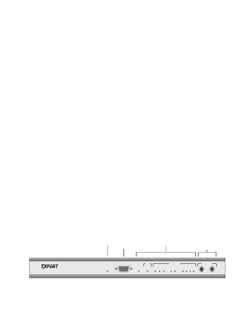
The PRISM 3301 front panel contains twelve LEDs indicating unit status. The
alarm messages associated with these indicators, including a date and time stamp,
are recorded one at a time in the Alarm Queue. Up to 100 alarm messages can be
stored in the alarm queue. When the alarm queue is full, the 101
st
message is
added and the 1
st
message is deleted. The Alarm Queue can be displayed using the
ASCII terminal command line interface or Verilink Manager. See Chapter 4 on
page 15 for more information concerning the PRISM 3301 terminal interface.
Whenever the PRISM 3301 encounters a failure on the near-end, it sends one or
more DS3/E3 alarm messages to the far-end announcing the near-end condition. The
following alarms are listed in order of priority (highest to lowest).
1. DS3 LOS/HBER
2. DS3 Out-of-Frame
3. DS3 AIS Received
4. DS3 Equipment Failure
Power
This LED is illuminated when there is power to the unit and the power supply is
operating normally.
Test
This LED is illuminated when the unit is in either Local DTE Loopback, Local
Line Loopback, Remote Line Loopback, or Remote Line Loop Up test mode.
If the T3 signal has been re-routed to the auxiliary BNC connector through a user
command, the TEST LED blinks once a second.
DTE Clock Loss
The PRISM 3301 reports DTE Clock Loss when the unit stops receiving the
Transmit Timing (TT) clock sent by the DTE. This is the Send Timing (ST) sent
by the PRISM 3301 and turned around by the DTE. When the unit again receives
the transmit clock, the alarm is cleared.
PRISM 3301
POWER
TEST
BPV
YEL
YEL
TX
LOSS
RX
AIS
AIS
TX
RX
MONITOR
NETWORK
DTE
SIG FRM
PAR
ERR
REM
PAR
ERR
CLOCK
LOSS
LOCAL ACCESS
Power
LED
ASCII
Terminal
Interface
Test & Alarm
LEDS
BNC
Access
Jacks
Figure 3-1 Front Panel LED Indicators
✍