Connection to the ports, Rgb in 1, Rgb in 2 – Dukane 8914 User Manual
Page 55: Rgb out, At rgb signal at component video signal, No connection), Ground, Y ground, Pin signal signal 1, Except for rgb out
3
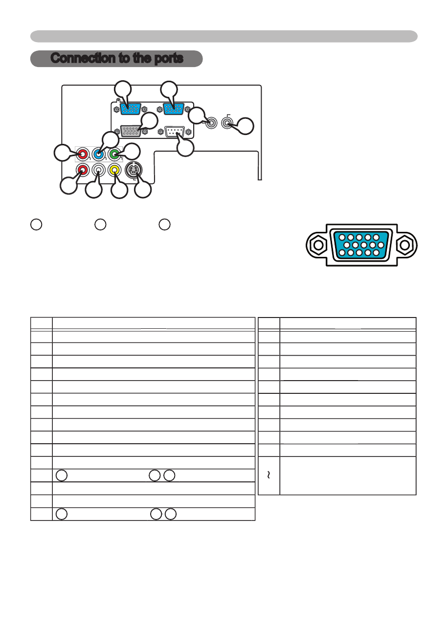
Connection to the ports
A
A
RGB IN 1,
B
RGB IN 2,
C
RGB OUT
D-sub 15pin mini shrink jack
• Video signal: RGB separate, Analog, 0.7Vp-p,
75Ω terminated (positive)
• H/V. sync. Signal: TTL level (positive/negative)
• Composite sync. Signal: TTL level
At RGB signal At component video signal
Pin
Signal
Signal
1 Video Red
2 Video Green
3 Video Blue
4 (No connection)
5 Ground
6 Ground Red
7 Ground Green
8 Ground Blue
9 (No connection)
10 Ground
11 (No connection)
12
A
A : SDA (DDC data),
: SDA (DDC data), B / C : (No connection)
: (No connection)
13 H. sync / Composite sync.
14 V. sync.
15
A
A : SCL (DDC clock),
: SCL (DDC clock), B // C : (No connection)
: (No connection)
Y
VIDEO
RGB IN1
RGB IN2
RGB OUT
CONTROL
AUDIO 1-IN
S-VIDEO
COMPONENT VIDEO
C
B
/P
B
C
R
/P
R
R-AUDIO 2-L
AUDIO-OUT
Connection to the ports
Pin
Signal
Signal
1
C
R
/P
R
2
Y
3
C
B
/P
B
4
(No connection)
(No connection)
5
Ground
6
C
R
/P
R
Ground
7
Y Ground
8
C
B
/P
B
Ground
9
(No connection)
(No connection)
10
Ground
11
15
(No connection)
* except for RGB OUT.
10
10 9
8
7
6
5
4
3
2
1
15
15 14
14 13
13 12
12 11
H
J
M
CONTROL
A
B
G
D
E
I
L
K
C
F