Tri Tool 224B Miter Mandrel User Manual
Page 16
92-0839
TRI TOOL INC.
16
NOTE:
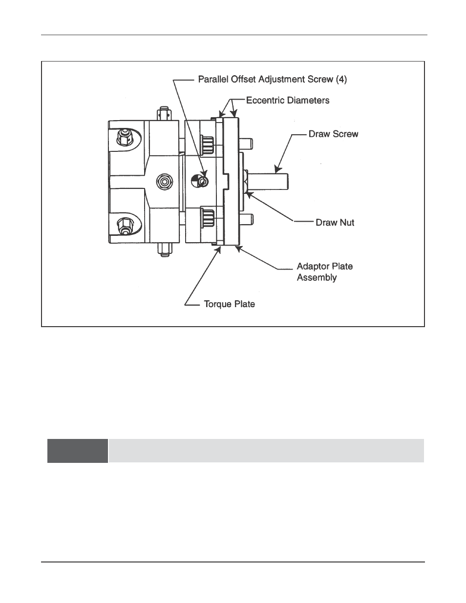
Leave the Draw Nut slightly loose during and after the Angular Offset adjustment.
Check to see that the Adaptor Plate Assembly is centered to the gimbal plate.
If not, locate the four parallel offset adjustment screws and back off one or two
screws where the Adaptor Plate Assembly is “in”.
Tightening to opposite one or two screws will bring the Adaptor Plate Assembly
toward the center.
To make the Parallel Offset adjustment, all (4) four screws must be slightly loose.
Once the Adaptor Plate Assembly has been roughly aligned and centered, tempo-
rarily snug all of the Adjustment Screws and the Draw Nut.
Insert the Miter Head into the workpiece.
Parallel offset adjustment
See also other documents in the category Tri Tool Equipment:
- 204B Cutting Head (9 pages)
- 204B Cutting Head (10 pages)
- 204B Cutting Head (9 pages)
- 212B Single Point Spring Hanger Assembly (8 pages)
- 204B Cutting Head (13 pages)
- 204B Cutting Head (36 pages)
- 204B Cutting Head (17 pages)
- 201BA Beveler (36 pages)
- 204B Elbow Mandrel (16 pages)
- 204B Beveler (45 pages)
- 204B Flange Facer (21 pages)
- 206B Elbow Mandrel (17 pages)
- 206B Flange Facer (22 pages)
- 206B Beveler (45 pages)
- 212B ID Tracking Module (17 pages)
- 206B Miter Mandrel (16 pages)
- 206B Sleeve Mandrel (13 pages)
- 208B Elbow Mandrel (20 pages)
- 208B ID Tracking Module (18 pages)
- 208B Miter Mandrel (20 pages)
- 208B Flange Facer (28 pages)
- 208B Sleeve Mandrel (15 pages)
- 212B Elbow Mandrel (16 pages)
- 214B Beveler Single Point Flange Facer (41 pages)
- 212B Flange Facer (22 pages)
- 212B Miter Mandrel (20 pages)
- 212B Single Point Hydraulic Motor Assembly (9 pages)
- 212B Single Point Flange Facer Miter Mandrel (28 pages)
- 212B Sleeve Mandrel (12 pages)
- 214B Elbow Mandrel (20 pages)
- 214B Flange Facer (23 pages)
- 214B ID Track Module (19 pages)
- 214B Miter Mandrel Head Kit (22 pages)
- 214B Sleeve Mandrel (13 pages)
- 236B ID Tracking Module (23 pages)
- 224B Single Point (30 pages)
- 230B Beveler Flange Facer (16 pages)
- 230B ID Tracking Module (15 pages)
- 230B Lifting Frame (19 pages)
- 236B Miter Mandrel (25 pages)
- 301SP Tube Squaring (35 pages)
- 236B Single Point (32 pages)
- 302 Tube Squaring Micro Feed Assembly (11 pages)
- 302 Tube Squaring (31 pages)