Tri Tool 224B Miter Mandrel User Manual
Page 15
15
Org 990702
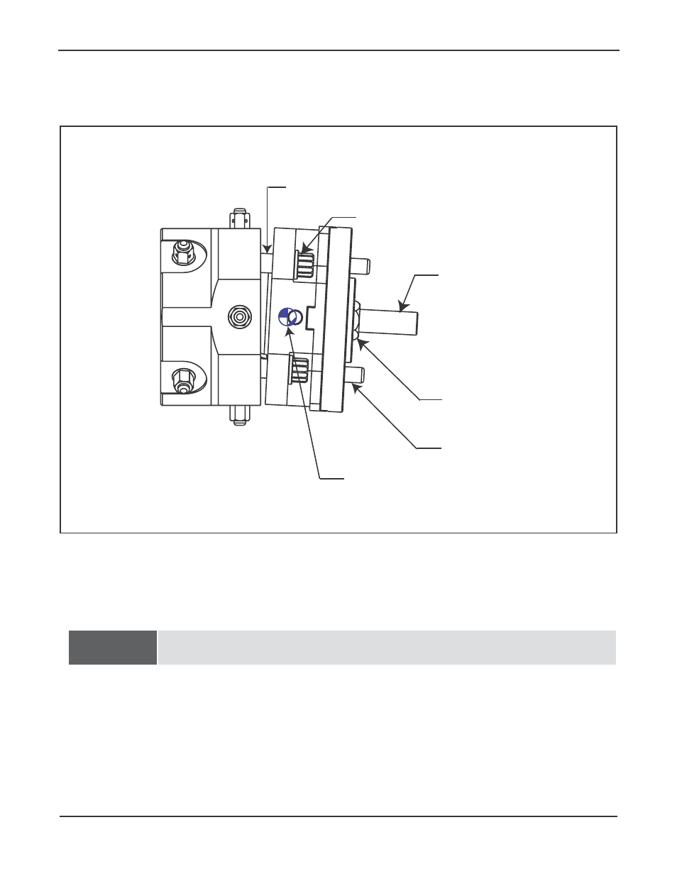
Model 224B Miter Mandrel Head
Check the gap between the Gimbal Plate and the Mandrel Head to see that it is
approximately even all around.
Uneven gap
Angular Offset Adjustment Screw (4)
Draw Screw
Draw Nut
Torque Pin (4)
Angular offset pivot point
Angular Offset Adjustment.
NOTE:
If it is not, then loosen the angular offset adjustment screw(s) where the gap is small
and tighten the Angular Offset Adjustment Screw(s) where the gap is wide.
Lightly tighten the Draw Nut.
All four of the Angular Offset Adjustment Screws must be used in conjunction with
each other.
All screws must be at least slightly loose to allow movement.
If the Mandrel Shaft is to be drawn directly toward one screw, the opposite screw
must be loosened far enough to allow for the take up before the near screw is
tightened.
- 204B Cutting Head (9 pages)
- 204B Cutting Head (10 pages)
- 204B Cutting Head (9 pages)
- 212B Single Point Spring Hanger Assembly (8 pages)
- 204B Cutting Head (13 pages)
- 204B Cutting Head (36 pages)
- 204B Cutting Head (17 pages)
- 201BA Beveler (36 pages)
- 204B Elbow Mandrel (16 pages)
- 204B Beveler (45 pages)
- 204B Flange Facer (21 pages)
- 206B Elbow Mandrel (17 pages)
- 206B Flange Facer (22 pages)
- 206B Beveler (45 pages)
- 212B ID Tracking Module (17 pages)
- 206B Miter Mandrel (16 pages)
- 206B Sleeve Mandrel (13 pages)
- 208B Elbow Mandrel (20 pages)
- 208B ID Tracking Module (18 pages)
- 208B Miter Mandrel (20 pages)
- 208B Flange Facer (28 pages)
- 208B Sleeve Mandrel (15 pages)
- 212B Elbow Mandrel (16 pages)
- 214B Beveler Single Point Flange Facer (41 pages)
- 212B Flange Facer (22 pages)
- 212B Miter Mandrel (20 pages)
- 212B Single Point Hydraulic Motor Assembly (9 pages)
- 212B Single Point Flange Facer Miter Mandrel (28 pages)
- 212B Sleeve Mandrel (12 pages)
- 214B Elbow Mandrel (20 pages)
- 214B Flange Facer (23 pages)
- 214B ID Track Module (19 pages)
- 214B Miter Mandrel Head Kit (22 pages)
- 214B Sleeve Mandrel (13 pages)
- 236B ID Tracking Module (23 pages)
- 224B Single Point (30 pages)
- 230B Beveler Flange Facer (16 pages)
- 230B ID Tracking Module (15 pages)
- 230B Lifting Frame (19 pages)
- 236B Miter Mandrel (25 pages)
- 301SP Tube Squaring (35 pages)
- 236B Single Point (32 pages)
- 302 Tube Squaring Micro Feed Assembly (11 pages)
- 302 Tube Squaring (31 pages)