Operation – Tri Tool 224B Miter Mandrel User Manual
Page 14
92-0839
TRI TOOL INC.
14
OPERATION
NOTE:
CAUTION:
Never attempt to manually lift the Mandrel with the BEVELMASTER™ installed.
The (8) eight Jackscrews are removable.
They are made of heat treated steel and have a slight spherical radius on the sur-
face that contacts the workpiece.
On most surfaces this provides for excellent holding power with virtually no marring
of the workpiece.
(3) Three lengths of jackscrews and (6) six lengths of spacers are provided.
An Extension Plate, which is also available, will extend the ID range.
Turn the Jackscrews to a diameter slightly smaller than the bore of the workpiece.
Combinations of Spacers will extend the ID Range.
Before the Miter Mandrel Head is mounted to the workpiece, both the Angular Off-
set and the Parallel Offset Adjustments should be approximately centered.
This will permit a maximum range of adjustment for final settings after the mandrel
has been mounted.
To make the Parallel Offset Adjustment, all (4) four screws must be slightly loose.
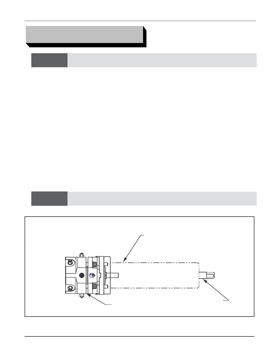
Mandrel Shaft Assembly and Draw Rod locations.
Miter Mandrel Head
Mandrel Shaft Aassembly
Draw Rod