Tri Tool 212B Single Point Flange Facer Miter Mandrel User Manual
Page 15
15
Model 212B Miter Mandrel Head for SP/FF
92-0738 : Rev. 980331
If not, locate the four (4) Parallel Offset Adjusting Screws and back off one (1)
or two (2) screws where the Adapter Plate Assembly is ‘in’.
Tightening to opposite one or two screws will bring the Adapter Plate Assembly
toward the center.
NOTE: To make the Parallel Offset adjustment. All four (4) screws must be
slightly loose.
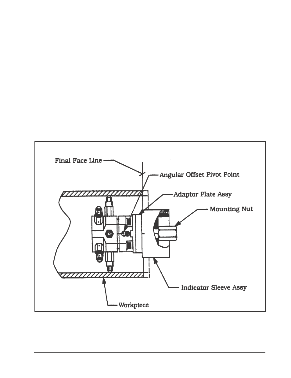
Once the Adapter Plate Assembly has been roughly aligned and centered,
temporarily snug all of the Adjustment Screws and the Draw Nut.
Insert the Miter Mandrel Head into the work-piece.
NOTE: It is highly desirable to mount the Miter Mandrel head so that Angular
Offset Pivot Point is on the same plane with the proposed finished weld
preparation.
Installation of the Indicator Sleeve Assembly
- 204B Cutting Head (9 pages)
- 204B Cutting Head (10 pages)
- 204B Cutting Head (9 pages)
- 212B Single Point Spring Hanger Assembly (8 pages)
- 204B Cutting Head (13 pages)
- 204B Cutting Head (36 pages)
- 204B Cutting Head (17 pages)
- 201BA Beveler (36 pages)
- 204B Elbow Mandrel (16 pages)
- 204B Beveler (45 pages)
- 204B Flange Facer (21 pages)
- 206B Elbow Mandrel (17 pages)
- 206B Flange Facer (22 pages)
- 206B Beveler (45 pages)
- 212B ID Tracking Module (17 pages)
- 206B Miter Mandrel (16 pages)
- 206B Sleeve Mandrel (13 pages)
- 208B Elbow Mandrel (20 pages)
- 208B ID Tracking Module (18 pages)
- 208B Miter Mandrel (20 pages)
- 208B Flange Facer (28 pages)
- 208B Sleeve Mandrel (15 pages)
- 212B Elbow Mandrel (16 pages)
- 214B Beveler Single Point Flange Facer (41 pages)
- 212B Flange Facer (22 pages)
- 212B Miter Mandrel (20 pages)
- 212B Single Point Hydraulic Motor Assembly (9 pages)
- 212B Sleeve Mandrel (12 pages)
- 214B Elbow Mandrel (20 pages)
- 214B Flange Facer (23 pages)
- 214B ID Track Module (19 pages)
- 214B Miter Mandrel Head Kit (22 pages)
- 214B Sleeve Mandrel (13 pages)
- 236B ID Tracking Module (23 pages)
- 224B Miter Mandrel (27 pages)
- 224B Single Point (30 pages)
- 230B Beveler Flange Facer (16 pages)
- 230B ID Tracking Module (15 pages)
- 230B Lifting Frame (19 pages)
- 236B Miter Mandrel (25 pages)
- 301SP Tube Squaring (35 pages)
- 236B Single Point (32 pages)
- 302 Tube Squaring Micro Feed Assembly (11 pages)
- 302 Tube Squaring (31 pages)