Tri Tool 212B Single Point Flange Facer Miter Mandrel User Manual
Page 13
13
Model 212B Miter Mandrel Head for SP/FF
92-0738 : Rev. 980331
This will permit a maximum range of adjustment for final settings after the mandrel
has been mounted.
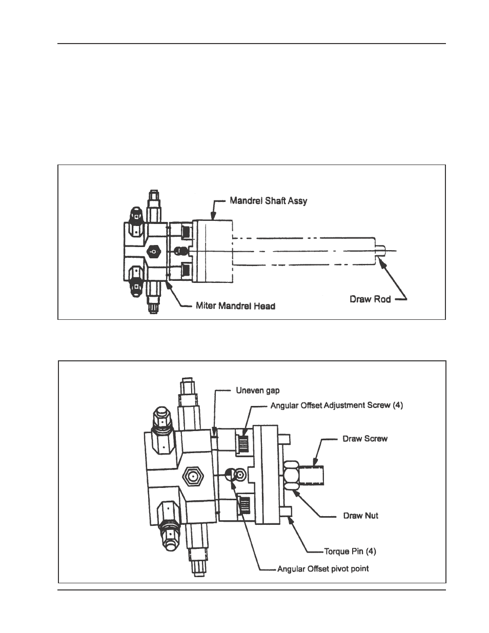
By turning the Draw Rod counterclockwise, the mandrel Shaft Assembly can be
removed from the Miter Mandrel Head.
NOTE: To make the parallel Offset Adjustment, all four (4) screws must be
slightly loose.
Check the gap between the Gimbal Plate and the Mandrel Head to see that it is
approximately even all around.
Angular Offset
Adjustmnet
Mandrel Shaft
Asst and Draw
Rod Locations
See also other documents in the category Tri Tool Equipment:
- 204B Cutting Head (9 pages)
- 204B Cutting Head (10 pages)
- 204B Cutting Head (9 pages)
- 212B Single Point Spring Hanger Assembly (8 pages)
- 204B Cutting Head (13 pages)
- 204B Cutting Head (36 pages)
- 204B Cutting Head (17 pages)
- 201BA Beveler (36 pages)
- 204B Elbow Mandrel (16 pages)
- 204B Beveler (45 pages)
- 204B Flange Facer (21 pages)
- 206B Elbow Mandrel (17 pages)
- 206B Flange Facer (22 pages)
- 206B Beveler (45 pages)
- 212B ID Tracking Module (17 pages)
- 206B Miter Mandrel (16 pages)
- 206B Sleeve Mandrel (13 pages)
- 208B Elbow Mandrel (20 pages)
- 208B ID Tracking Module (18 pages)
- 208B Miter Mandrel (20 pages)
- 208B Flange Facer (28 pages)
- 208B Sleeve Mandrel (15 pages)
- 212B Elbow Mandrel (16 pages)
- 214B Beveler Single Point Flange Facer (41 pages)
- 212B Flange Facer (22 pages)
- 212B Miter Mandrel (20 pages)
- 212B Single Point Hydraulic Motor Assembly (9 pages)
- 212B Sleeve Mandrel (12 pages)
- 214B Elbow Mandrel (20 pages)
- 214B Flange Facer (23 pages)
- 214B ID Track Module (19 pages)
- 214B Miter Mandrel Head Kit (22 pages)
- 214B Sleeve Mandrel (13 pages)
- 236B ID Tracking Module (23 pages)
- 224B Miter Mandrel (27 pages)
- 224B Single Point (30 pages)
- 230B Beveler Flange Facer (16 pages)
- 230B ID Tracking Module (15 pages)
- 230B Lifting Frame (19 pages)
- 236B Miter Mandrel (25 pages)
- 301SP Tube Squaring (35 pages)
- 236B Single Point (32 pages)
- 302 Tube Squaring Micro Feed Assembly (11 pages)
- 302 Tube Squaring (31 pages)