Thermon Heat Transfer Compounds User Manual
Page 8
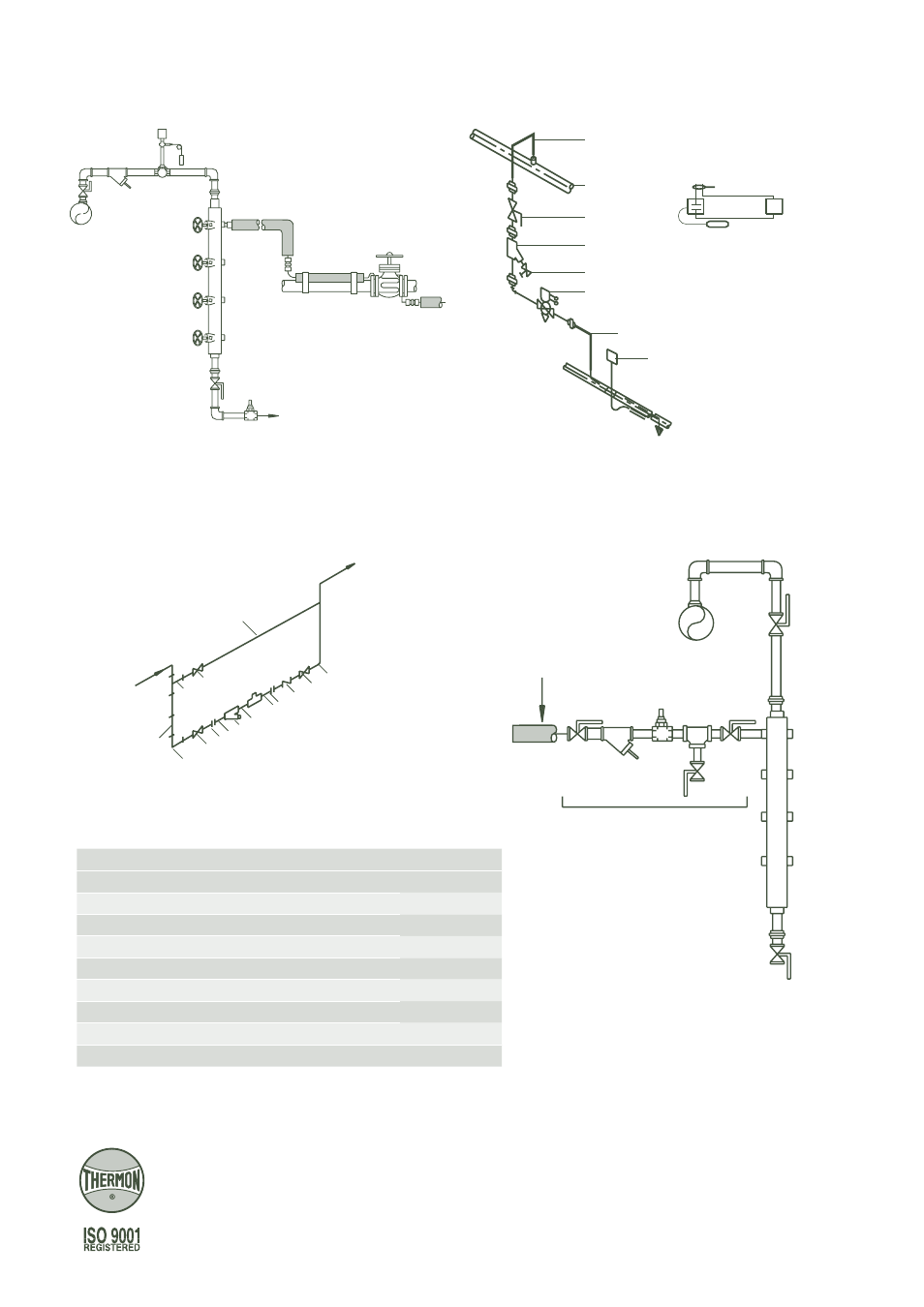
Illustration H: Temperature Control Details
Illustration I: Trapping and Condensate Handling Details
Steam Temperature Control Using Self-Actuated
Mechanical Controller with Prefabricated Manifold
Steam Temperature Control Using Thermostat and Solenoid
Valve for Pipe or Ambient Sensing (Field Assembly)
ThermoTube
®
Steam Supply
Manifold
Steam
Header
Note . . .
Controllers are available
for pipewall sensing.
To Nearest Condensate Return Point
Strainer
Typical for
Ambient Sensing
ThermoTube
Steam Header
Strainer
Solenoid Valve
Isolation Valve
Blowoff Valve
ThermoTube
Thermostat
(Pilot Duty Only)
Thermostat
Power Supply
Sensing Bulb
Solenoid Valve
Note . . .
Thermostat bulb should be
located approximately
90° from the tracer.
8
4
7 2
6 2
27
5
1
Trap
3
8
ThermoTube From
Steam Tracer
9
4
ThermoTube to
Condensate Return Header
Bypass Line
(Optional)
Trap Station
Condensate
Header
Condensate
Return Manifold
From Steam
Tracer
Field Fabricated Trapping Assembly
Prefabricated Trap Station
and Condensate Manifold
Form T
SP0023U-1209 © T
hermon Manufacturing Co. Printed in U.S.A.
Corporate Headquarters
100 Thermon Dr.
•
PO Box 609
San Marcos, TX 78667-0609
•
U.S.A.
Phone: +1 512-396-5801
•
Facsimile: +1 512-396-3627
THERMON . . . The Heat Tracing Specialists
®
www.thermon.com
European Headquarters
Boezemweg 25
•
2641 KG Pijnacker
PO Box 205
•
2640 AE Pijnacker
•
The Netherlands
Phone: +31 (0) 15-36 15 370
•
Facsimile: +31 (0) 15-36 15 379
Item No.
Description
Size
1
Pipe SMLS Schedule 80 CS PE ft
12 mm
2
Nipple Schedule 80 CS TBE
12 mm x 80 mm
3
Gate Valve 600 LB CS SCRD 12CR RP
12 mm
4
Globe Valve 600 CS SCRD 12CR TR
12 mm
5
Check Valve 600 LB CS SCRD 12CR LIFT
12 mm
6
Y-Strainer 600 LB CS SCRD
12 mm
7
Union 3000 LB CS SCRD
12 mm
8
Elbow 3000 LB CS SCRD
12 mm
9
Tee Schedule 80 CS
12 mm