Installation procedures, T-3 and t-99 – Thermon Heat Transfer Compounds User Manual
Page 3
INSTALLATION PROCEDURES
T-3 and T-99 . . .
Installation on Straight Run Piping
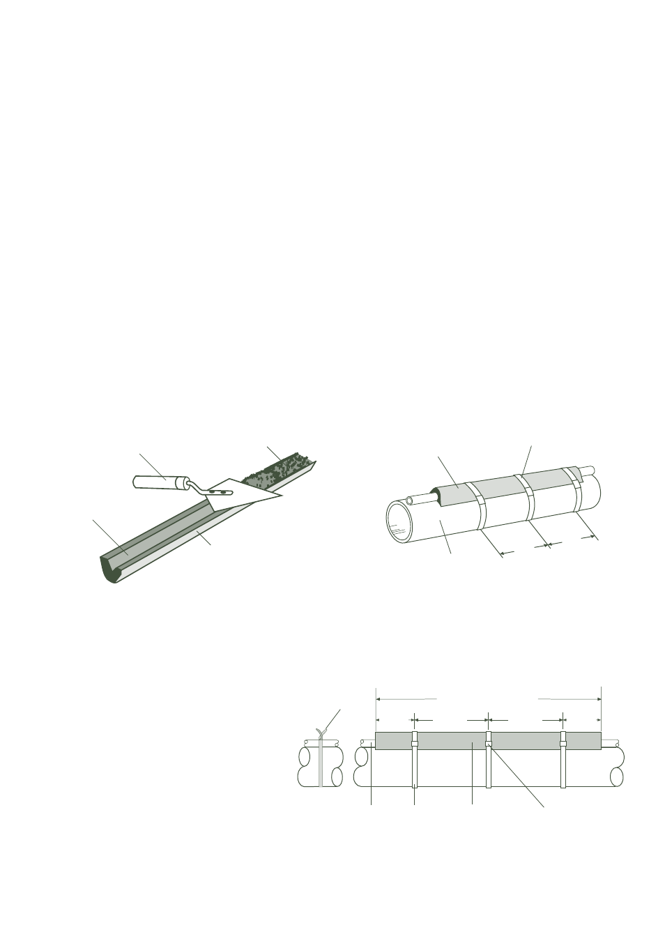
1. Install tube tracers in accordance with Illustrations A and B
below. Pressure test tracing for leaks with steam pressure
equal to or greater than the normal operating pressure or
preferably with suitable hydrostatic tests. Repair any leaks
and retest until the tracing system is free of leaks.
2. Fill TFK channel with T-3 or T-99 compound and use
trowel to groove compound for tube tracer. The trowel
should be used to remove heat transfer compound from
the channel leaving a “V” groove. The mass of compound
removed corresponds to the space which will be occupied
by the tracer tube.
3. Press TFK channel over tracer.
4. If two or more tracers are used, they should be equally
spaced circumferentially around the pipe in accordance
with Illustration E on page 4.
5. Attach channel to process piping with stainless steel band-
ing and crimp-type seals as shown.
• Banding should be a minimum of 12 mm x 0.5 mm for
TFK-4 systems.*
• Banding should be a minimum of 12 mm x 0.5 mm for
TFK-7 or TFK-9 systems.*
• Banding tool should exert a force of 4450 N or greater.*
* Banding, crimp seals and tools meeting the required specifications are available
from Thermon.
6. Insulate and weatherproof piping.
Note . . .
T-3 and T-99 grades are water-soluble and should never be exposed to moisture. In
all places where heat transfer compound has been applied with a hand trowel and the
compound is exposed, temporary weather protection is required. Polyethylene film
placed over heat transfer compound provides excellent weather protection. Remove film
prior to installing insulation. For applications above 210°C channels should be stainless
steel versus galvanized metal.
2
1. Band with minimum of 12 mm x 0,5 mm band-
ing. For temporary attachment, secure with 1
mm stainless steel wire.
2. Place ChannelTrace
TM
system or SnapTrace
®
with
channel over tracer after removing the wire.
1.22 m
380 mm
Stainless Steel
Banding
Crimp Seals
Tracer
Temporary
Stainless Steel
Tie Wire
TFK Channel
(SnapTrace or
ChannelTrace)
380 mm
230 mm
230 mm
Illustration B: Installation of Tube Tracers
Illustration A: Installation of ChannelTrace System
TFK Channel
Heat Transfer
Compound
Hand Trowel
“V” Groove
TFK Channel
Stainless Steel
Banding
Process Piping
Press filled TFK channel over tracer and secure to process
pipe using stainless steel banding.
Fill TFK channel with compound and use trowel to groove
compound for tracer.
380
mm
380
mm