Heat transfer compounds, Installation on valves, flanges, elbows and pumps – Thermon Heat Transfer Compounds User Manual
Page 4
Heat Transfer Compounds
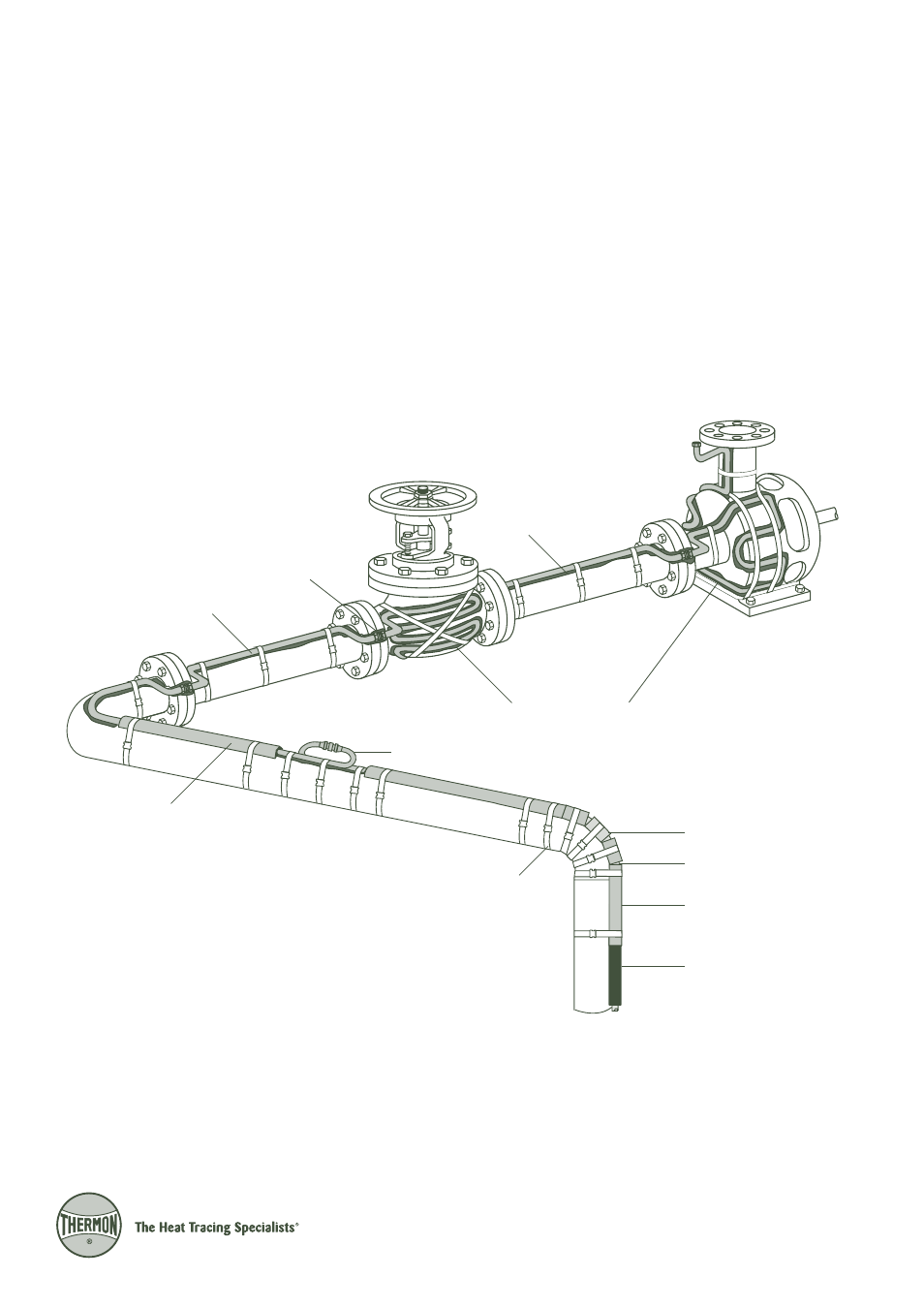
Illustration C: Heat Transfer Compound Installation
Installation on Valves, Flanges,
Elbows and Pumps . . .
1. Install tube tracers in accordance with Illustration C below.
Pressure test tracing for leaks with steam pressure equal
to or greater than the normal operating pressure, or pref-
erably with suitable hydrostatic tests. Repair any leaks and
retest until the tracing system is free of leaks.
2. Hand trowel heat transfer compound over tracers so that
the tracer tube is completely embedded in compound (see
illustration below). Fill all voids between surface and tracer
3
to ensure maximum heat transfer. Cure the heat transfer
compound. If the maximum thickness of the compound
is greater than 25 mm, best results and more rapid overall
application will be obtained by installing these particular
grades in two layers with an air drying time of at least 24
hours between applications.
3. Insulate and weatherproof equipment.
Heat Transfer Compound
Fillet Application
T-80 or T-85
Heat Transfer
Compound
T-80 or T-85
Heat Transfer
Compound
TFK Channel
Tubing Connection
(Optional)
(Typical)
Stainless Steel
Banding
Short Sections
of TFK Channel
Tracer
TFK Channel
T-3, T-99 or SnapTrace
Tubing Connection