Thermo Technologies SMT 400 User Manual
Page 21
20
3.7
STATUS SCREEN - SYSTEM DIAGNOSTICS
1
SMT 400 2.0
00 18 F2
COL SEN:
RET SEN:
TNK1 SEN:
38 C0 00
29 C0 00
38 C0 00
36 C0 00
PMP 1
PMP 2 PMP 3 ZUS 1 ZUS 2
AUTO
1
0
AUTO AUTO AUTO AUTO
0
0
0
0
1
1
1
1
33.5 °C
23.5 °C
74.0 °C
54.0 °C
TNK2 SEN:
1
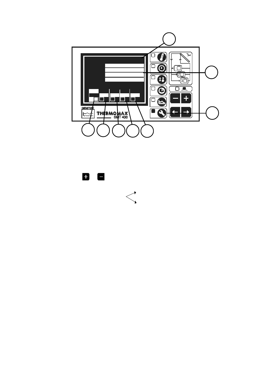
Status Screen function selector
Pressing this key reveals the Status Screen as shown above.
2
Pump 1 Relay Status.
The output status of the Pump 1 relay may be viewed here, or altered by
pressing the
or
key when the RELAY window is selected.
“0” = Relay Manually OFF
a frame around ‘0’ indicates Relay OFF
“AUTO” = For normal operation
“1” = Relay Manually ON
a frame around ‘1’ indicates Relay ON
3
Pump 2 Relay Status.
The output status of the Pump 2 relay may be viewed or changed here (as
above).
4
Pump 3 Relay Status.
The output status of the Pump 3 relay may be viewed or changed here (as
above).
5
Auxiliary Output 1 Relay Status.
The output status of the Auxiliary Output 1 relay may be viewed or changed
here (as above).
6
Auxiliary Output 2 Relay Status.
The output status of the Auxiliary Output 2 relay may be viewed or changed
here (as above).
7
Electronic Signature.
Each SMT 400 has its own Electronic Signature which is used in the factory
for date of manufacture information.
8
Sensor Calibration and Status Windows.
These windows display sensor calibration data and also the temperature
reading for all sensors.
7
5
8
1
2
3
4
6