SVS MINI 7EX 110V User Manual
Page 6
•
As a reminder, clear all persons and obstructions from the Lift's path during its operation. Keep fingers
and other objects away from the scissors and other moving parts. Technical personnel should always be
present whenever the Lift is in the Service mode.
5. CONSIDERATION FOR LIFT PLACEMENT
•
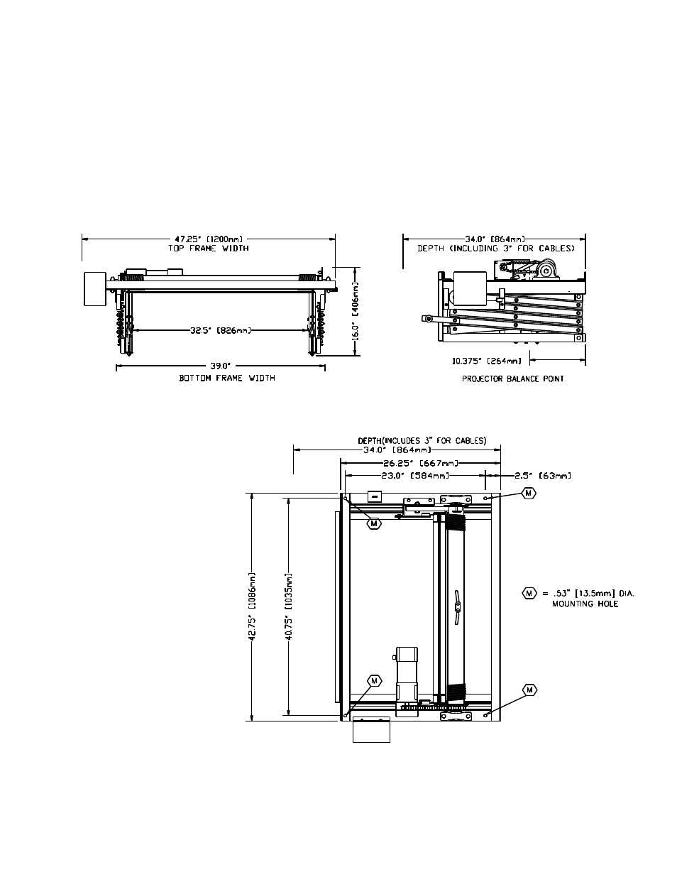
Before beginning the installation, check the dimensions of the lift against the available space above the
ceiling. Be sure to include the projector lens and any accessories which may add to the overall
dimensions
•
Preliminary measurements should also be made to layout the orientation of the projector and lift to the
screen. Consider if the lens is offset from the center of the projector and thus the center of the Lift.
6. LIFT SUPPORTING STRUCTURE
The SVS Mini 7EX Lift should be
mounted from four 1/2” rods. The
mounting hole locations are
marked with a
The thread rods must be supported
by a rigid structure. If the threaded
rods exceed more than 2-feet (0.6
M) from the support structure to
the lift's top mounting holes cross
bracing should be installed
between the support rods. Figure 4
shows the cross bracing and the
correct height for mounting the lift
above the false ceiling.
SVS Mini 7EX Lift Installation Instructions
Page 6 of 17
Figure 2. SVS Mini 7EX Front & Side Views
Figure 3. SVS Mini 7EX Top View