Super Systems 9120 RPSC User Manual
Page 6
Model 9120 Redundant Probe System - Color
4580 – Redundant Probe System – Color
Page 6 of 23
Using the operator interface shown below you can configure the Model 9120-RPS per these instructions
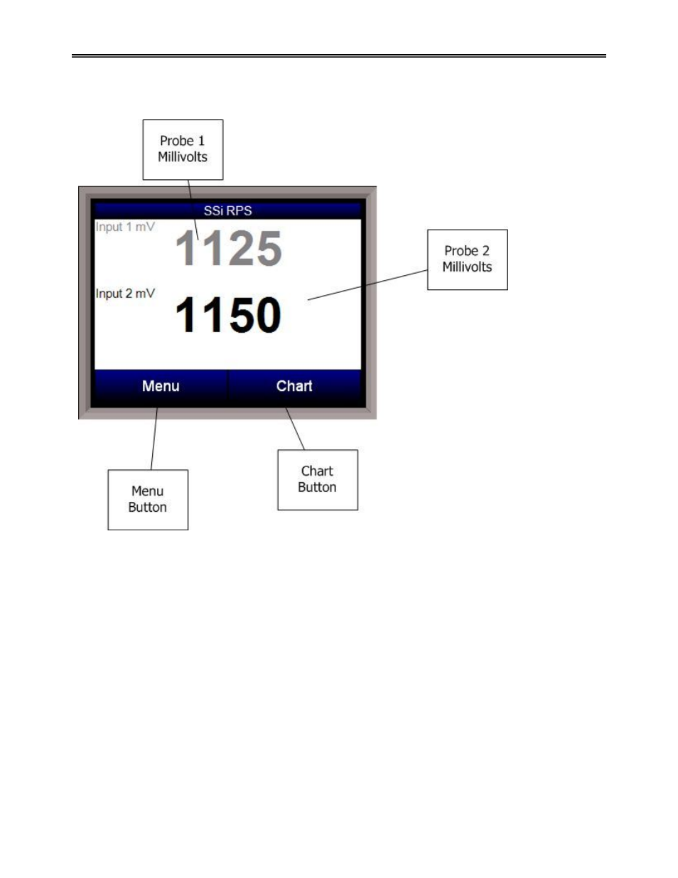
Main Overview Screen
The Main Overview screen will be the initial screen that is displayed when the RPS is first started up. The
Main Overview screen will display: the two probes’ millivolts values, as well as the Menu button and the
Chart button. The active probe will be displayed in Black, while the inactive probe will be displayed in
Gray
. Any activated output will be lit up on the RPS unit. Any error or message will be displayed above the
Menu and Chart buttons.
The list of runtime messages is:
•
Probe
n
active – indicates which probe is selected. This message may be followed by:
o Selection
n
forced by digital input – Indicates that the selected probe has been forced
by digital input. Digital input 1 selects probe 1; input 2 selects probe 2.
o User controlled – Indicates that the probe has been manually selected by the operator.
o Out of band condition detected – Indicates that the current probe has just gone out of
band
o Changing to probe
n
in
mm
minutes
ss
seconds – Indicates that the specified probe
will be selected in the time frame provided. The message will count down while the timer
is active.
The list of error conditions is:
•
Both inputs less than 950 mV – Neither probe can be selected when both inputs are less than
950 mV.
•
Input
n
over 1300 mV – The indicated input is over range.