Super Systems 9120 RPSC User Manual
Page 12
Model 9120 Redundant Probe System - Color
4580 – Redundant Probe System – Color
Page 12 of 23
2400
19200
76800
4800
28800
115200
9600
38400
Slave 2 Mode
This will allow the user to set the Slave 2 mode.
Note – This is configurable, but currently, it is not
used with the RPS
. The options are: MMI, Modbus, ADAM, SSi Analog Input Board, or
Yokogawa.
IP Address
This option will allow the user to modify the IP
address of the
9120 Instrument
only. The address
must be supplied in a 999.999.999.999 format, or it
will not be accepted. Contact Super Systems at 800-
666-4330 or your IT department before changing any
of the IP addresses.
Subnet Mask
This option will allow the user to modify the IP subnet
mask of the
9120 Instrument
only. The address must
be supplied in a 999.999.999.999 format, or it will not
be accepted. Contact Super Systems at 800-666-
4330 or your IT department before changing any of
the IP addresses.
Gateway
This option will allow the user to modify the IP gateway of the
9120 Instrument
only. The address must be
supplied in a 999.999.999.999 format, or it will not be accepted. Contact Super Systems at 800-666-4330
or your IT department before changing any of the IP addresses.
Analog Input Setup
The 9120 controller has two analog inputs. Each of
the inputs comes with a factory default
configuration dependent on the application (refer to
PVT type under the
Furnace Setup
section). It can
be modified prior to shipment to your facility or in
the field by a technician or qualified/trained person
with the proper security code.
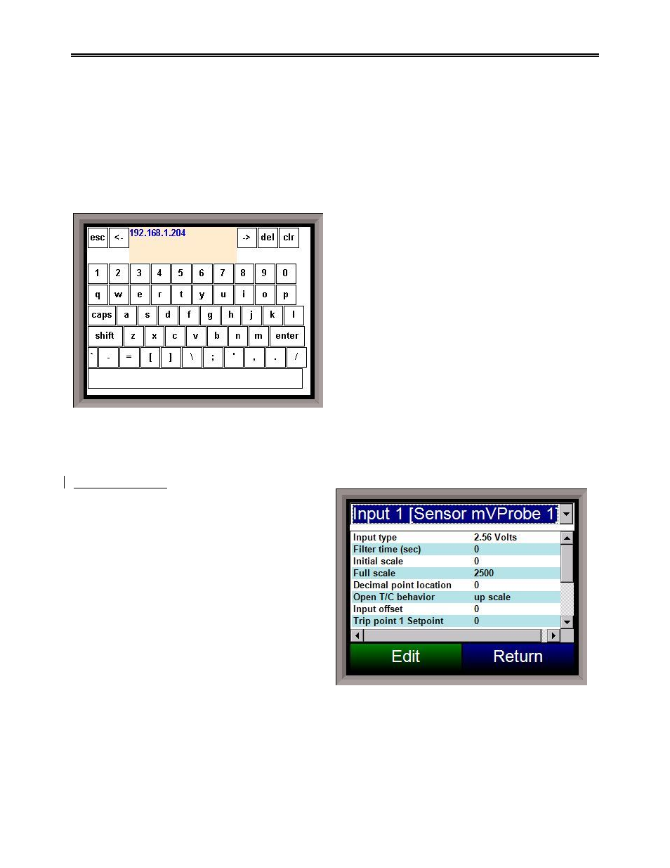
Analog Input Terminals
Analog Input 1 – terminals 31 and 32
Analog Input 2 – terminals 29 and 30
For the RPS, the default input type is 2.5
Volts, with a range of 2500
.
Input Type
The thermocouple type for most applications can be
modified depending on your specific needs. Please note that in some applications, some of the inputs DO
NOT allow the user to modify the Input type.
Note: Before changing the input type, make sure to set the
appropriate jumpers, if necessary
.
The jumper will need to be manually changed on the input board before
changing the input type to a 10:1 setting (non-thermocouple types)
. To change the Input type, first select
which input you want to change by selecting it in the pull-down menu at the top of the screen. Once
selected, click
OK
and the displayed Input type under Value will be the current type.