Super Systems 7EK 31082 User Manual
Page 7
2
GB
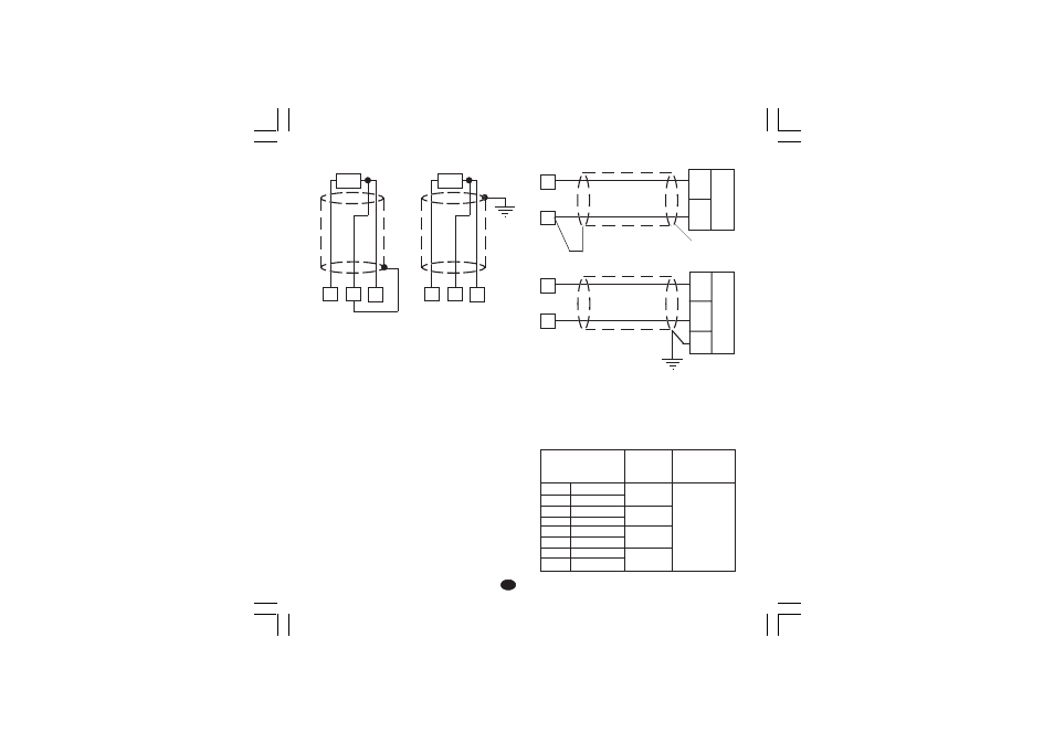
LINEAR INPUT
Fig. 4 mA, mV AND V INPUTS WIRING
NOTE:
1) Don’t run input wires together with power cables.
2) Pay attention to the line resistance; a high line
resistance may cause measurement errors.
3) When shielded cable is used, it should be grounded at
one side only to avoid ground loop currents.
4
RTD
1
3
4
RTD
1
3
Shield
_
+
mA,
mV
or
V
3
+
_
G
mA
mV
or
V
1
3
1
RTD INPUT
Fig. 3 RTD INPUT WIRING
Input circuit: current injection (135
mA).
Line resistance: automatic compensation up to 20
W/wire
with no measurable error.
Calibration: according to DIN 43760
NOTE:
1) Don’t run input wires together with power cables.
2) Pay attention to the line resistance; a high line
resistance may cause measurement errors.
3) When shielded cable is used, it should be grounded at
one side only to avoid ground loop currents.
4) The resistance of the 3 wires must be the same.
Input type
13
14
15
16
17
18
19
20
0 - 60 mV
12 - 60 mV
0 - 20 mA
4 - 20 mA
0 - 5 V
1 - 5 V
0 - 10 V
2 - 10 V
impedance
> 1 M
W
< 5
W
> 200 k
W
> 400 k
W
Accuracy
0.2 % + 1 digit
@ 25°C
XKSser1-A0.p65
10/19/01, 1:37 PM
2