Troubleshooting – Super Systems SuperOX User Manual
Page 7
Super Systems Inc. Page 7 of 14
SuperOX
TM
Operations Manual
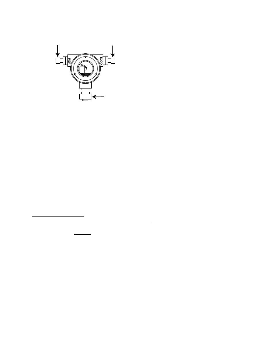
Figure 6
Wire designation:
White (Sensor +)
Black (Sensor -)
Green (Thermocouple +)
Red (Thermocouple - )
Troubleshooting
When trouble arises with an oxygen control system, it is important to establish where the
problem is located: the sensor, signal transmission lines, the control instrument, or the
combustion chamber itself. Several simple tests can help to isolate the problem quickly. It is
most important to first understand the nature of the fault. Aside from erratic behavior like
cycling, or failure to stabilize at the setpoint, the most common symptom is non-conformity of
the work pieces to quality assurance specifications.
To evaluate most faults, the recommended tools are:
1. A 3 1/2-digit millivoltmeter with at least 10 M
Ω input impedance and 0 to 1999 mV range;
2. A temperature calibrator; and
3. A simulator to output 0 to 200 millivolts at less than 50 M
Ω output impedance.
Sensor troubleshooting: In order to establish the source of problems in your installation, first
avoid removing the SuperOX
TM
Sensor from the furnace.
All of the following meaningful
questions must be answered while your sensor is at temperature and is exposed to a normal
atmosphere under manual control:
1. Are the connections from the T/C extension wire and sensor cable clean and firmly
attached at the correct sensor and control instrument terminals? Note that the shield
wire in the sensor cable should be connected to ground at the control instrument end
only!
2. Is the sensor impedance less than 50 KΩ at temperatures above 1550°F? Conduct the
test shown in Figure 3 using a shunt resistor of about 100 KΩ. Measure the voltage EC
before shunting, then EM with the shunt in place. Calculate RP. If it exceeds 50 KΩ,
proceed to step 6 below.
3. How quickly does the sensor react to a change in O2 concentration? Read the sensor
millivolts with the controller or the digital meter. Short the sensor for 5 seconds,
remove the short and measure the time required to return to within 1% of the original
reading. If it exceeds 60 seconds, proceed to step 6, below.
Reference
Air
Cooling
Air
Cable
Entry