Fifo, 1 fifo – Sundance SMT401 User Manual
Page 15
Released
Page 15 of 21
SMT401 PMC TIM Carrier User Guide
Document Name:
SMT401 User Guide V1.2.doc
Issue : 02
Rev.: 1.11
32 bit
Add
Ctr
FIFO
16
x
32
FIFO
16
x
32
PCI
ADI
O
Add
Data
C40
Decoder
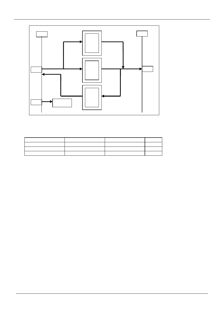
The C40 can access any PCI location but in should be noted that data written
and read will always be long word aligned and 32 bits wide. The table below
illustrates the available registers.
Address Register(Write)
Register(Read)
Width
C0000000
FIFO FIFO 32
C0400000 PCI
Address
-
32
C0800000 Control -
2
4.3.1 FIFO
The SMT401 PMC incorporates 16 deep x 32 wide FIFO buffers on both read
and write paths between the C40 and PCI bus. The FIFO is only effective
when burst mode is enabled in the control register. With burst mode disabled,
the bridge will request the PCI bus for each word transferred.
With burst mode enabled, data written to the empty FIFO will be absorbed
until 16 words make the FIFO full. This state will trigger a PCI burst write of
16 words in length thus transferring 64 bytes to the destination. The FIFO
can be written with the next 16 words during the PCI burst transaction to
maintain throughput. The C40 may incur wait states if the FIFO becomes full
during this time.
For burst mode read transactions, reading from the empty FIFO will trigger a
PCI burst of 16 words from source memory, filling the FIFO with 64 bytes of
data. The C40 will be able to read the first word of data as soon as it is
loaded into the FIFO from the PCI bus.
Transfers to / from the PCI space may not always be a multiple of 16 words.
In this case, the burst mode bit must be turned off to perform single transfers
for each word. For example, a transfer of 100 words could be performed as
follows :-
Product Name:
SMT401
Revision Date:
07 December 2004
Author:
Mark I. Cartlidge (Updated by SM, added JTAG slave section)
Original Date:
12 May 1999