Additional details – Studio Technologies 76 V.1.04 User Manual
Page 6
Issue 4, September 2008
Model 76/77 User Guide
Page 6
Studio Technologies, Inc.
for Surround
connects to a Model 76 Central Controller
using a 9-pin cable. A major strength of the
Model 77 is its ability to confi gure, under
software control, many important operating
parameters.
Additional Details
The Model 77 provides fi ve buttons and
associated LEDs for selection of the sur-
round and stereo input sources to be moni-
tored. While in most cases only one input
source will be monitored at a time, stereo
input C can be selected for simultaneous
monitoring with one of the two surround
or other two stereo inputs. This allows
the two selected inputs to be combined
(“summed”).
The surround and stereo monitor output
levels can be controlled by way of a large,
easy-to-use rotary control. The level con-
trol auto mute all function ensures that
the monitor output channels automatically
mute whenever the output level is set to
the full attenuation (minimum) position. By
using the reference level function, the moni-
tor output level can set to a pre-confi gured
value. This is provided for audio-with-picture
applications that require a specifi c monitor
level. The reference level is easily confi g-
ured by taking an electronic “snapshot” of
the desired monitor output level. For opera-
tor confi rmation a 4-digit LED readout dis-
plays the level of the monitor output. It can
be confi gured to display either the attenua-
tion level or the sound pressure level (SPL).
The dim function allows the monitor output
level to be reduced by a fi xed dB amount.
The dim level is selected from four available
levels. A mute all function allows all monitor
output channels to be simultaneously mut-
ed. The channel mute/solo section provides
individual channel control. One pushbutton
switch sets the operating mode for either
mute or solo. In the mute mode, individual
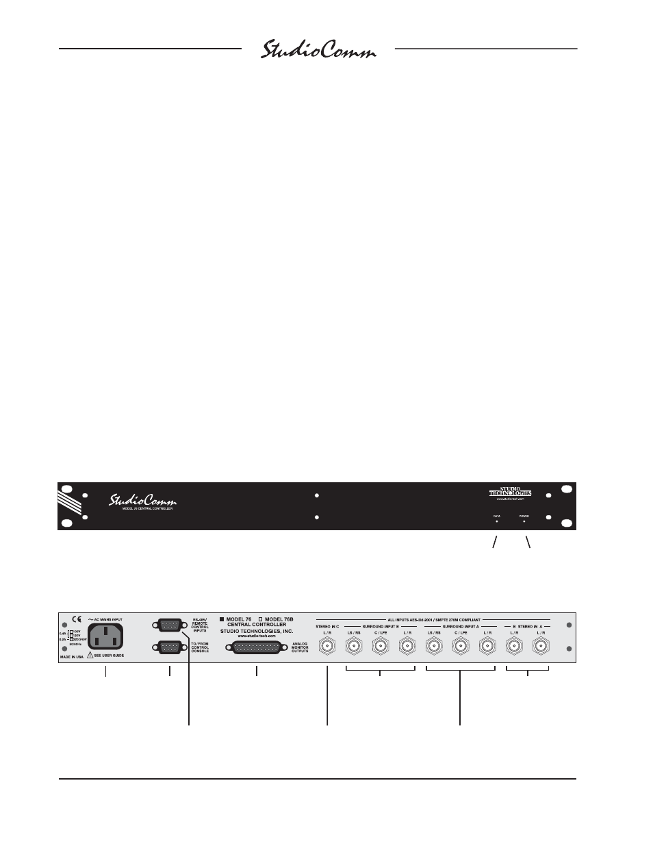
Figure 1. Model 76 Central Controller Front Panel
Figure 2. Model 76 Central Controller Back Panel
Power
present LED
Control console
data active LED
Stereo Input C
connection
Analog monitor
output connections
To/from
Model 77
Control
Console
AC mains
input connection
Remote control
inputs
Surround Input B
connections
Surround Input A
connections
Stereo Input A and
Stereo Input B
connections