Advanced operation, Adjusting the line input trim pots – Studio Technologies M233-01151 User Manual
Page 34
Issue 5, November 2014
Model 233 User Guide
Page 34
Studio Technologies, Inc.
Advanced
Operation
Adjusting the Line Input
Trim Pots
As has been previously mentioned, associ-
ated with the two line inputs are trim pots
that allow the input levels to be adjusted.
The two trim pots are accessible by way
of round openings in the bottom of the
Model 233’s enclosure. By adjusting these
trim pots, signals with a nominal level of
–12 dBV to +6 dBu can be effectively used
as cue sources. Unfortunately, there are no
definitive rules regarding how best to adjust
the trim pots, but some suggestions may
prove to be valuable. Depending on how the
line inputs are utilized, the trim pots can be
used to either adjust the absolute level of
each line input signal, or to adjust the rela-
tive level of the signals when compared to
other sources. The following examples may
provide some clarification.
Let’s begin with an application that has
a stereo cue source connected to the line
inputs. The cue source selection switches
are configured to create a stereo head-
phone output with line input 1 assigned to
the left channel and line input 2 assigned
to the right channel. Begin the trim pot
adjustment process by moving the user
level controls (located on the front panel)
to their detent (50% of rotation) positions.
Then, with the stereo cue source providing
signal at its normal level, adjust the trim pots
to provide a comfortable level to the con-
nected headphones. The user can now, in
response to changing conditions, adjust the
front-panel level controls as desired. Return-
ing the controls to their detent positions will
always provide the “reference” level to the
headphone output.
A second example has the intercom input
and line input 1 both providing cue sourc-
es. Pin 2 of the intercom circuit supplies
program-with-interrupt audio that is routed
to the headphone output’s left chan-
nel. Pin 3 of the intercom circuit supplies
program-only audio that is routed to the
right channel. Line input 1 is connected to
an audio source associated with a sports-
event “spotter” position. This source is
routed to the headphone output’s right
channel. The input trim pot associated
with line input 1 can now serve a critical
role—adjusting the relative level of the
“spotter” audio as compared to the level
of intercom pin 3. The trim pot allows the
desired “mix” to be created, providing the
user with an effective cue signal.
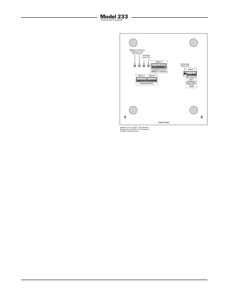
Figure 23. Bottom view showing line input and
talkback-to-intercom sidetone trim pots