Operating modes – Studio Technologies M233-01151 User Manual
Page 22
Issue 5, November 2014
Model 233 User Guide
Page 22
Studio Technologies, Inc.
can be changed even while the Model 233
is powered up and operating. The unit’s
operating characteristics will change in
“real-time” in response to configuration
changes.
In addition to the switch assemblies SW3
and SW4, the last two positions of switch
assembly SW2 are used for configuration.
Specifically, SW2-11 and SW2-12 are used
for the talkback to intercom functions.
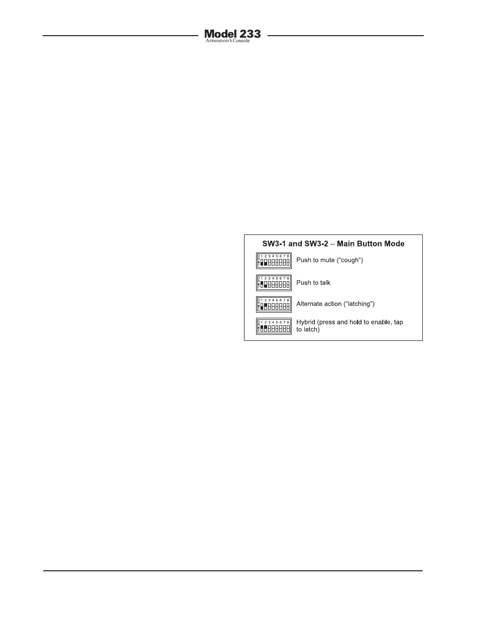
Main Output Button Mode
Switches SW3-1 and SW3-2 configure
how the main output button functions.
(“pots”) can be used to create the desired
“mix” of signals being sent to the head-
phone outputs. Many, many applications,
especially in production settings, can
benefit from this capability. The desired
cue sources must be carefully assigned
to take advantage of the monaural mode.
The first cue source should be assigned,
using the DIP switches, to the far left chan-
nel. Its output level will be adjusted by the
left control. The second cue source should
be assigned to the right channel. Its out-
put level will be adjusted by the far right
control. A third cue signal, sidetone, can
also be enabled. The sidetone level con-
trol, located on the far right, will be used
to adjust its level.
There is one limitation related to the head-
phone output mode. It’s the fact that the
output will be 2-channel monaural. What-
ever signal is present on the headphone
output’s left channel will also be present
on the right channel. A stereo headphone
mix can’t be created. But in most cases
this limitation won’t overshadow the ben-
efit of being able to create the mix. For
signal-flow clarification please review the
block diagram located at the end of this
user guide.
Operating Modes
The sixteen switches associated with
switch assemblies SW3 and SW4 are
used to configure the Model 233’s operat-
ing modes. Technically, these switches
“talk” to the microcontroller integrated
circuit and associated software that give
the Model 233 its “smarts.” The software
has been carefully designed to provide
a number of different ways in which the
unit can function. It’s critical to carefully
review the available options and choose
the ones that best meet the needs of a
specific application. Note that switches
Figure 8. Main output button mode settings
There are four available modes:
• Push to mute: In this mode the main
output is normally active. The main
output will mute whenever the button is
pressed and held. This is the “cough”
mode typically used for on-air sports
broadcasting applications.
• Push to talk: In this mode the main out-
put is normally muted. The main output
will become active whenever the button
is pressed and held.
• Alternate action: In this mode the main
output will change between its active
and muted state whenever the button
is pressed. Upon power up the main
output will be in its muted state.