Studio Technologies 212 2006 User Manual
Page 21
Model 212 User Guide
Issue 3, July 2006
Studio Technologies, Inc.
Page 21
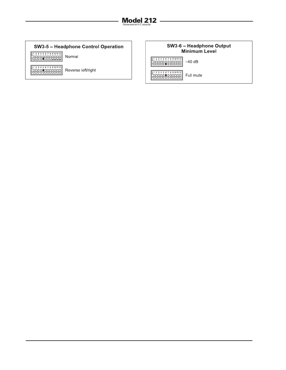
As you may have already guessed, when
selecting the reverse left/right mode of
operation everything is reversed! To be
more specific, when selected for reverse
mode, and the level/level mode is also
selected, the left control adjusts the head-
phone output’s right channel (output
jack’s ring lead) while the right control
adjusts the left channel. When selected to
the reverse mode, and the level/balance is
also selected, turning the balance control
in the counterclockwise direction increas-
es the perceived level of the right channel
output, and vice versa.
The reverse mode is provided specifically
for cases where a headset’s left and right
ear pieces are placed on a user’s head
in a reverse orientation. This ensures
that the user is provided with a consistent
and easy-to-use set of headphone level
controls.
Minimum Level Mode
Switch SW3-6 is used to configure the
headphone output’s minimum level. In the
–40 dB mode the minimum headphone
output level is 40 dB below maximum. The
headphone output channels will never fully
mute. This ensures that any audio signal
present on the selected cue audio source
will always be present on the headphone
output. In most on-air broadcast applica-
tions this is the appropriate setting.
Figure 12. Headphone output minimum level
settings
When the full mute mode is selected,
and the level/level mode is also selected,
moving either control to its fully counter-
clockwise position will cause its associ-
ated channel to fully mute.
When the full mute mode is selected, and
the level/balance mode is also selected,
turning the level control to its fully coun-
terclockwise position will cause both
headphone channels to mute. Turning the
balance control to either its fully clock-
wise or fully counterclockwise position will
cause the appropriate channel to mute.
Selecting the full mute mode may be
appropriate for applications where mini-
mizing the chance of audio “leakage”
is important. This could occur when the
connected headset or headphones are at
times placed on a desk or tabletop.
Digital Input Source
Switches SW3-7 and SW3-8 are used to
select which one of the three digital inter-
faces will be used by the Model 212 as its
audio source and reference clock input.
The two audio channels associated with
the selected digital input can be assigned
to the headphone output channels. In
addition, the clock signal derived from the
selected digital input is used by the digi-
tal audio circuitry. This clock signal is the
master “sync” reference that the Model
Figure 11. Headphone control operation
settings