Headphone output mode – Studio Technologies 212 2006 User Manual
Page 18
Issue 3, July 2006
Model 212 User Guide
Page 18
Studio Technologies, Inc.
A more complex application might have a
2-channel digital audio signal connected
to the Model 212, with an optional line
input card installed. Line-level audio from
a golf event “spotter” is connected to the
line input. In a case such as this, it would
be typical for digital input channel 1 to
be assigned to the headphone’s left
channel, digital input channel 2 assigned
to the right channel, and auxiliary input 1
also assigned to the right channel. This
would allow both digital input channel
2 and “spotter” audio to be heard in the
headphone’s right-channel output. To
achieve this would require that switches
SW2-1, SW2-6, and SW2-7 be placed in
their on positions. Note that using another
Studio Technologies 200-series announc-
er’s console at the “spotter” location could
also prove effective. It would provide all
the necessary microphone preamplifier,
talkback routing, and headphone monitor-
ing resources.
In some cases a user may wish to wear a
headset or a pair of headphones in a left/
right orientation opposite of what’s usual.
In this situation the transducer designated
for the left ear would actually supply audio
to the user’s right ear, and vice versa.
A specific application where this can
occur is when on-air talent needs to have
a headset’s boom microphone come
across the right side of their face, rather
than the more-typical left side. In this case
it’s important to select the left- and right-
channel headphone source assignment
accordingly. With the Model 212’s flexible
source selection there’s no reason why
users, such as on-air talent, shouldn’t
have their cue sources assigned correctly.
There may be cases where a monaural
“single-muff” headset or headphone will
be connected to the Model 212’s head-
phone output. In this case the desired cue
source(s) should be routed only to the left
channel. No sources should be assigned
to the right channel. This will eliminate the
short-circuit current that could occur when
a 2-conductor (monaural) plug is mated
with the Model 212’s 3-conductor (stereo)
headphone output jack.
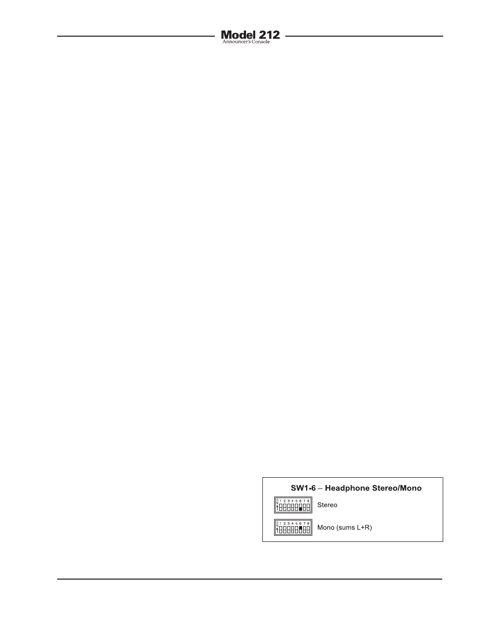
Headphone Output Mode
Switch SW1-6 allows a monaural head-
phone output to be created. This is
accomplished by summing (adding) the
selected left- and right-channel cue sig-
nals. The combined signals are sent to
both the left- and right-channel headphone
output driver circuits. The outputs of these
circuits connect, by way of 51 ohm series
protection resistors, to the headphone
output jack.
The headphone output monaural mode
feature was specifically included so that
a special “2-channel headphone mix”
mode can be created. By enabling the
mono mode, the two front-panel user level
controls (“pots”) can be used to create
the desired “mix” of signals being sent
to the headphone output. Many applica-
tions, especially in production settings,
can benefit from this capability. The
desired cue sources must be carefully
assigned to take advantage of the monau-
ral mode. The first cue source should be
Figure 7. Headphone output mode settings