Headphone source selection – Studio Technologies 212 2006 User Manual
Page 17
Model 212 User Guide
Issue 3, July 2006
Studio Technologies, Inc.
Page 17
could occur with a special Model 212 ap-
plication. But with a microphone connected
as the input source one should never use
the 0 dB setting. The issue is that with no
gain added to the microphone input signal,
the relative noise floor on the main and
talkback output channels will be much too
high. In conclusion, the 0 dB gain setting
doesn’t highlight a problem, but simply
reflects the unit’s gain structure.
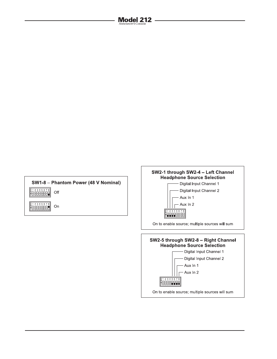
Phantom Power
The Model 212 can provide “48 volt”
phantom power to the microphone input.
Switch SW1-8 controls whether or not
phantom power is active. By phantom
power’s very nature it could be left applied
to the microphone input at all times. But
generally people prefer to turn it off unless
it is required for a specific microphone.
Figure 6. Left and right channel headphone
source selection settings
Figure 5. Phantom power switch settings
input cards have been installed. Alternate-
ly, a special Model 212 configuration may
have been implemented that uses one or
both of the auxiliary inputs.
Each of the available input sources can be
assigned to the headphone output’s left
channel, right channel, or both the left and
right channels. The Model 212’s circuitry
allows any combination of input assign-
ments to be made. For example, consider
the situation where a single digital input
channel is actively connected to the Model
212. In this case it may be desirable to
assign this signal to both the left and right
headphone channels. This would entail
setting switches SW2-1 and SW2-5 to their
on positions. All other switches would
remain in their off positions.
Headphone Source Selection
Switch assembly SW2 is used to configure
the source or sources that are routed to
the stereo headphone output. Up to four
sources may be available with the choices
being digital input channel 1, digital input
channel 2, auxiliary input 1, and auxiliary
input 2. The digital input channels are pro-
vided by the selected digital input source.
The digital input source is configured
from these choices: the AES3id input, the
optional AES3 input, or the bidirectional
digital interface. The auxiliary inputs are
analog and available only if optional line