Microphone preamplifier gain and phantom power – Studio Technologies 212 2006 User Manual
Page 15
Model 212 User Guide
Issue 3, July 2006
Studio Technologies, Inc.
Page 15
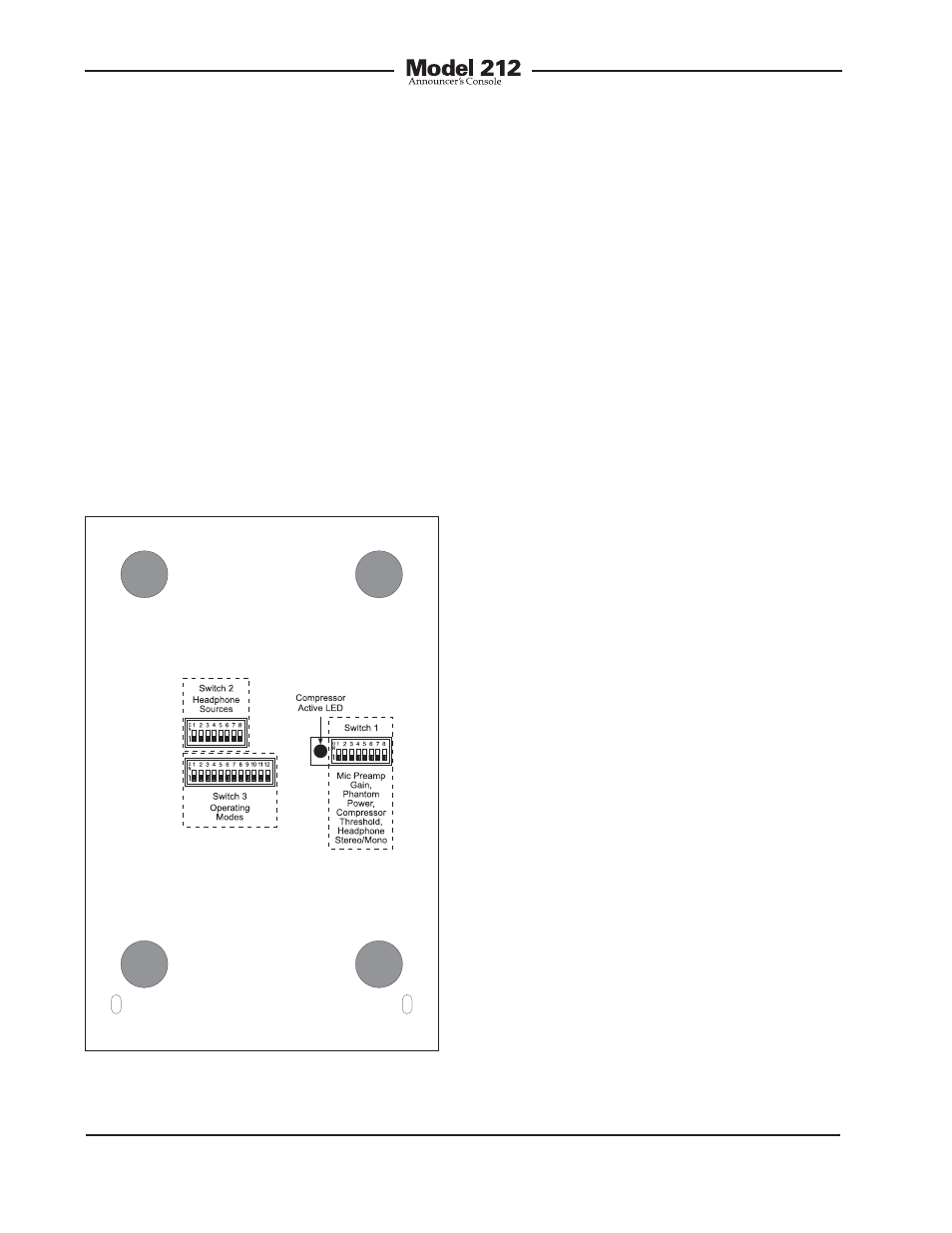
These switch assemblies are referred to
as Switch 1, Switch 2, and Switch 3, with
individual switches designated as SW1-1,
SW1-2, etc. The switch assemblies are ac-
cessed through openings in the bottom of
the Model 212’s enclosure. The enclosure
does not have to be disassembled to gain
access to the switches.
To prevent unauthorized personnel from
changing the configuration settings, a
security plate is attached to the bottom
of the Model 212’s enclosure. For conve-
nience, a configuration settings label is
attached to the security plate. It provides a
summary of the configurable parameters
and related information. Refer to Ap-
pendix A for a representative view of the
label. The security plate is held in place by
means of four rubber bumpers (“feet”) that
have built-in screws. Using your fingers,
remove the four bumpers so that the plate
can be removed. Refer to Figure 3 for a
detailed view of the configuration switch
assemblies.
Microphone Preamplifier Gain
and Phantom Power
Five switches are used to set the gain of
the microphone preamplifier. One switch
is used to select the on/off status of the
phantom power supply.
Microphone Preamplifier Gain
Switches SW1-1 through SW1-5 are used
to select the gain of the microphone
preamplifier. The choices are 10, 20, 30,
40, and 50 dB. Only one switch should
be enabled at a time. There’s no problem
changing the gain setting while the unit
is operating. Audio clicks or pops might
occur during gain transitions, but this
shouldn’t be a major issue as long as
associated monitor loudspeakers are
temporarily attenuated or muted.
Selecting the correct amount of gain for
an application might take a little experi-
mentation. The goal is to bring the mic’s
signal level up such that the main and talk-
back output levels will match the Model
212’s nominal digital output level which
is –20 dBFS. Operating at this signal level
will help to ensure the delivery of “clean”
audio with adequate level “headroom.”
The output of the Model 212’s microphone
preamplifier is routed to the input of the
compressor circuit.
Unfortunately, there’s no “perfect” gain
setting that this guide can recommend.
Figure 3. Bottom view of Model 212 showing
configuration switches and compressor active
LED