Studio Technologies 212 2006 User Manual
Page 16
Issue 3, July 2006
Model 212 User Guide
Page 16
Studio Technologies, Inc.
The two issues that impact the setting
are output sensitivity of the connected
microphone and the acoustical output
level of the microphone’s user. With
some headset microphones, such as the
Sennheiser HMD25, selecting an initial
setting of 30 dB is appropriate. Users
who speak loudly might need to have
the gain reduced to 20 dB. Quiet users
might need 40 dB of gain.
An LED indicator is provided as an aid
in correctly setting the gain of the micro-
phone preamplifier. Red in color, this LED
is located adjacent to switch assembly 1.
It is visible by observing the bottom of the
Model 212’s enclosure when the security
plate has been removed. Technically, this
red LED lights whenever the compres-
sor circuitry is controlling the dynamic
range of the signal coming from the mi-
crophone preamplifier. Using configura-
tion DIP switch SW1-7, the compressor’s
threshold will be set to either –14 or –4
dBFS. (Details concerning setting the
compress threshold are discussed later
in this user guide.) If the threshold is set
for –14 dBFS a good “rule of thumb” is to
adjust the gain of the microphone preampli-
fier such that the compressor active LED
will light (“flash”) only when the connected
microphone is sending signal peaks. Dur-
ing normal operation the LED should never
remain fully lit when audio of typical signal
level is present on the mic input.
If the threshold is set for –4 dBFS the LED
should light only on extreme signal peaks,
or possibly never. This is because with a
–4 dBFS threshold the compressor is in-
tended only to prevent signals from ever
causing the maximum digital level of 0
dBFS to be reached. It’s not supposed
to reduce the dynamic range of normal
program material. As an aid in setting the
microphone preamplifier’s gain, it might
useful to temporary set the compressor’s
threshold to –14 dBFS. Once the gain has
been set so that the LED lights only on
peaks the threshold can be returned to the
–4 dBFS setting.
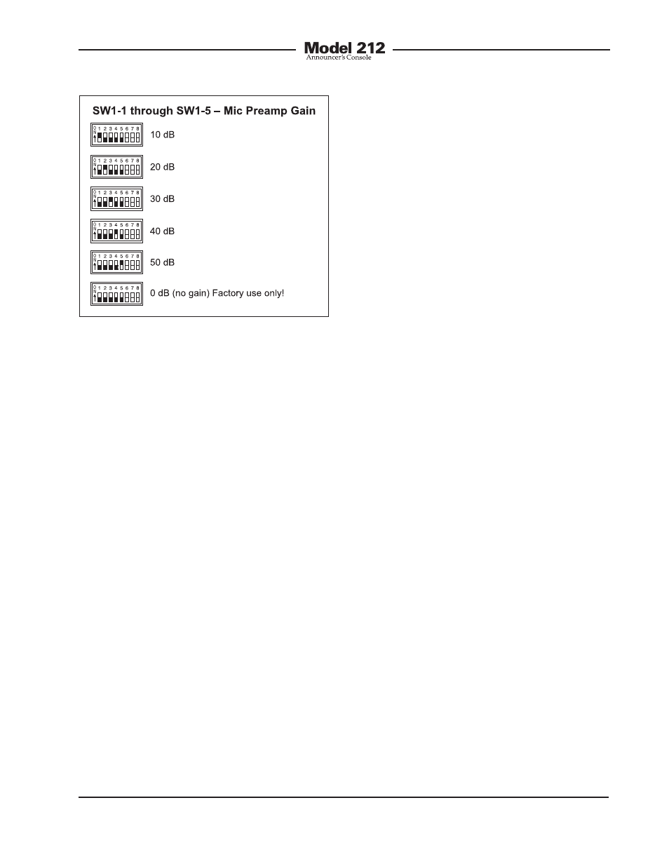
It’s expected that the 10 and 50 dB gain
settings will not be often used. But there
are always exceptions and that’s why they
are included. It’s possible that with a very
“hot” microphone, such as a phantom-
powered condenser-type, 10 dB of gain
could be correct. It’s also possible that a
microphone with a very low-level output,
such as a ribbon-type, would need 50 dB
of gain. But in general, the 20, 30, and
40 dB gain settings will serve most
applications.
Note that if no gain switch is set to its active
(on) position the preamplifier will operate
at unity (0 dB) gain. In this mode the pre-
amplifier will remain stable, but is intended
for use only during factory testing. A valid
exception would be where a line-level signal
is connected to the microphone input. This
Figure 4. Microphone preamplifier gain switch
settings