21 3.4 diagnostic leds – Smart Avi RGB2VGA User Manual
Page 21
INSTALLATION
21
3.4 Diagnostic
LEDs
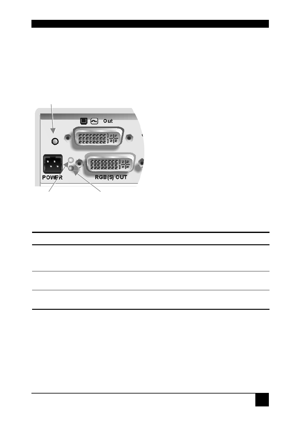
Each RGB to DVI(/VGA) Converter is fitted with three indicator LEDs: Monitor Detect,
Device Ready and Video Signal. The Monitor Detect LED is to the left of the video output
connector. The Device Ready and Video Signal LEDs are next to the Power socket.
The location of the LEDs is shown below:
Monitor Detect
Video Signal
Device Ready
(Green)
(Red)
Figure 3
Diagnostic LEDs on RGB to DVI(/VGA) Converter
LED Appearance
Diagnostics
Monitor Detect
On
Flashing
Off
Attached DVI monitor (TFT) detected
Attached VGA monitor (CRT) detected
No monitor detected
Device Ready
(Red LED)
Off
On
Device not ready
Device ready
Video Signal
(Green LED)
Off
On
No video signal or valid mode detected
Attached and valid mode detected
- HDCVX (2 pages)
- XTPRO (2 pages)
- VSA-100 (2 pages)
- XTAV (2 pages)
- XTWALL (2 pages)
- HDX-PRO (2 pages)
- UTX-500 (2 pages)
- UXPRO (2 pages)
- UX-PLUS (2 pages)
- XTPro Xtreem (8 pages)
- DVX-100 (2 pages)
- DVX-200 (2 pages)
- DVX-PRO (2 pages)
- DVX-PLUS (2 pages)
- FDX-2000 (2 pages)
- DVX-Multi (2 pages)
- UDX-Plus (2 pages)
- DVX-200-Pro (2 pages)
- SDX (2 pages)
- SDX-Plus (2 pages)
- RK-DVX2U-A (2 pages)
- UDX-2P (2 pages)
- DVX2U (2 pages)
- DVX4P (2 pages)
- SDX-2P (2 pages)
- RK-DVX-Plus (2 pages)
- HDX-100 (2 pages)
- RK-DVX200 (8 pages)
- HDX-Plus (2 pages)
- HDX Ultra (2 pages)
- HDX-400 (2 pages)
- HFX-TX/RX (2 pages)
- USB2-Mini (2 pages)
- USB2Pro (2 pages)
- USBXpress (2 pages)
- USB-100 (2 pages)
- AR-100 (2 pages)
- HDCIR (2 pages)
- VS2P (2 pages)
- VS8P (2 pages)
- AVS4P (2 pages)
- VCT-400 (2 pages)
- VCA-400 (2 pages)
- XT-TX1600 (2 pages)
- HDC-400 (2 pages)