Chapter 6: encoder interface, 1 overview, 2 configuration – Sensoray 2426 User Manual
Page 9: 3 encoder connector, 4 wiring, 1 interfacing rs-422 signals
2426 Instruction Manual
7
Encoder Interface
Chapter 6: Encoder Interface
6.1 Overview
The 2426 module includes a fast, bidirectional counter that is
optimized for use with incremental encoders and other high
frequency pulse generators. The counter has 32-bit resolution
to enable encoder position to be tracked for extended periods
without client intervention, and its high speed operation
enables high resolution, fast moving encoders to be tracked
without errors. The counter is zeroed upon module reset.
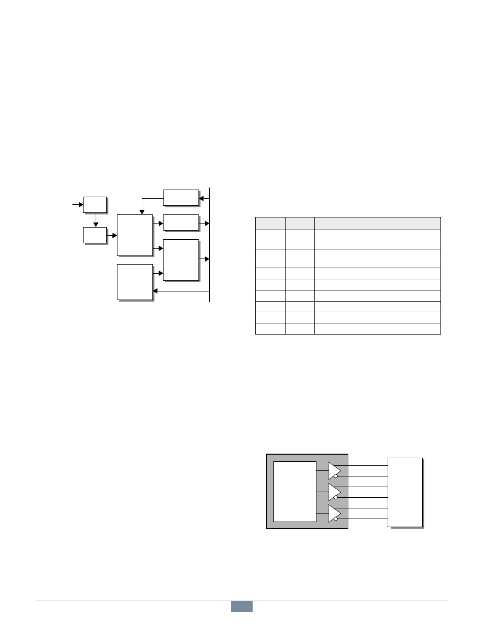
Figure 5: Encoder Interface Block Diagram
Quadrature encoders commonly generate three signals: two
clocks (A and B) and one index, whereas devices such as
tachometers produce only a single clock and no index. Some
encoders produce an Index output while others do not. The
ENC connector supports all three of these signals.
Encoder inputs are first applied to input buffers that accept
TTL, 5V CMOS, or differential RS-422 signals. The
conditioned inputs are then synchronized to the system clock
domain and processed by a quadrature decoder FSM.
The interface includes a preload register which may be loaded
with any client-specified 32-bit value. Optionally, the value
stored in this register may be synchronously copied into the
counter in response to an edge event on the Index input. The
Preload register is zeroed upon module reset.
ENC lights briefly when the encoder counter value
changes in response to incoming clock pulses.
6.2 Configuration
Before starting encoder operation, the client will typically issue
a “WEM” shell command to write to the Mode register. The
Mode register is logically partitioned into fields that control
various aspects of encoder interface operation:
• Clock mode/multiplier specifies whether the interface
will operate in quadrature mode (with x1, x2 or x4
multiplier) or non-quadrature mode (basic pulse counting,
up count only).
• Preload enable specifies whether the occurrence of an
active edge on the Index input will cause the counter to be
parallel loaded from the preload register.
• Active index edge selects either the rising or falling edge
of the Index input as the active edge.
6.3 Encoder Connector
The ENC connector (see Figure 2 for connector location) is
used to make all encoder connections to the 2426 module.
6.4 Wiring
6.4.1 Interfacing RS-422 Signals
The encoder interface employs differential RS-422 line
receivers to buffer all incoming signals. Each line receiver has
“+” and “-” inputs for connecting to a differential signal pair.
Use both of these inputs for encoders that employ RS-422
signals, as shown in Figure 6.
Figure 6: Connecting RS-422 Encoder Signals
If you are interfacing a single-clock device (e.g., tachometer),
connect its clock output to the A clock inputs and leave the ±B
clock inputs disconnected. If you are not using the Index
signal, leave the ±Index inputs disconnected.
I
n
t
e
r
n
a
l
D
a
t
a
B
u
s
Decoder
FSM
32 Bit
Preload
Register
Status
Register
Mode
Register
Counter
Input
Buf
Encoder
Signals
Input
Sync
Table 3: ENC Connector Pin Assignments
Pin
Name
Function
4, 9
GND
Ground reference for encoder power and all
encoder signals.
5
+5VOUT
+5VDC output. This can be used to supply
operating power to an encoder.
1
+A
Clock A positive input.
6
-A
Clock A negative input.
2
+B
Clock B positive input.
7
-B
Clock B negative input.
3
+X
Index positive input.
8
-X
Index negative input.
A
Encoder
+A
-A
2426 ENC
B
+B
-B
X
+X
-X