Chapter 2: introduction, 1 overview, 2 status leds – Sensoray 2426 User Manual
Page 4: 3 heartbeat, 4 module reset, 1 rst pushbutton, 2 config pushbutton
2426 Instruction Manual
2
Introduction
Chapter 2: Introduction
2.1 Overview
Sensoray’s Model 2426 is a compact electronics module that
performs I/O interface services for Ethernet clients. A variety
of interfaces are implemented on the module including:
• Analog output (AOUT).
• 6 analog inputs.
• 8 optically isolated, general-purpose digital inputs.
• 16 general-purpose digital outputs (DOUT) with integral
routing system for safety interlocks.
• Incremental encoder interface.
• Serial RS-422/485 communication port.
The module includes a number of hardware features that are
designed to simplify its integration into host systems: it is
compact, it requires only a single 24VDC power source, and it
can be quickly installed by simply snapping it onto a standard
din mounting rail. The module’s software interface is simple,
too: I/O services are provided over Telnet for automated
applications, and HTTP for diagnostic and manual control.
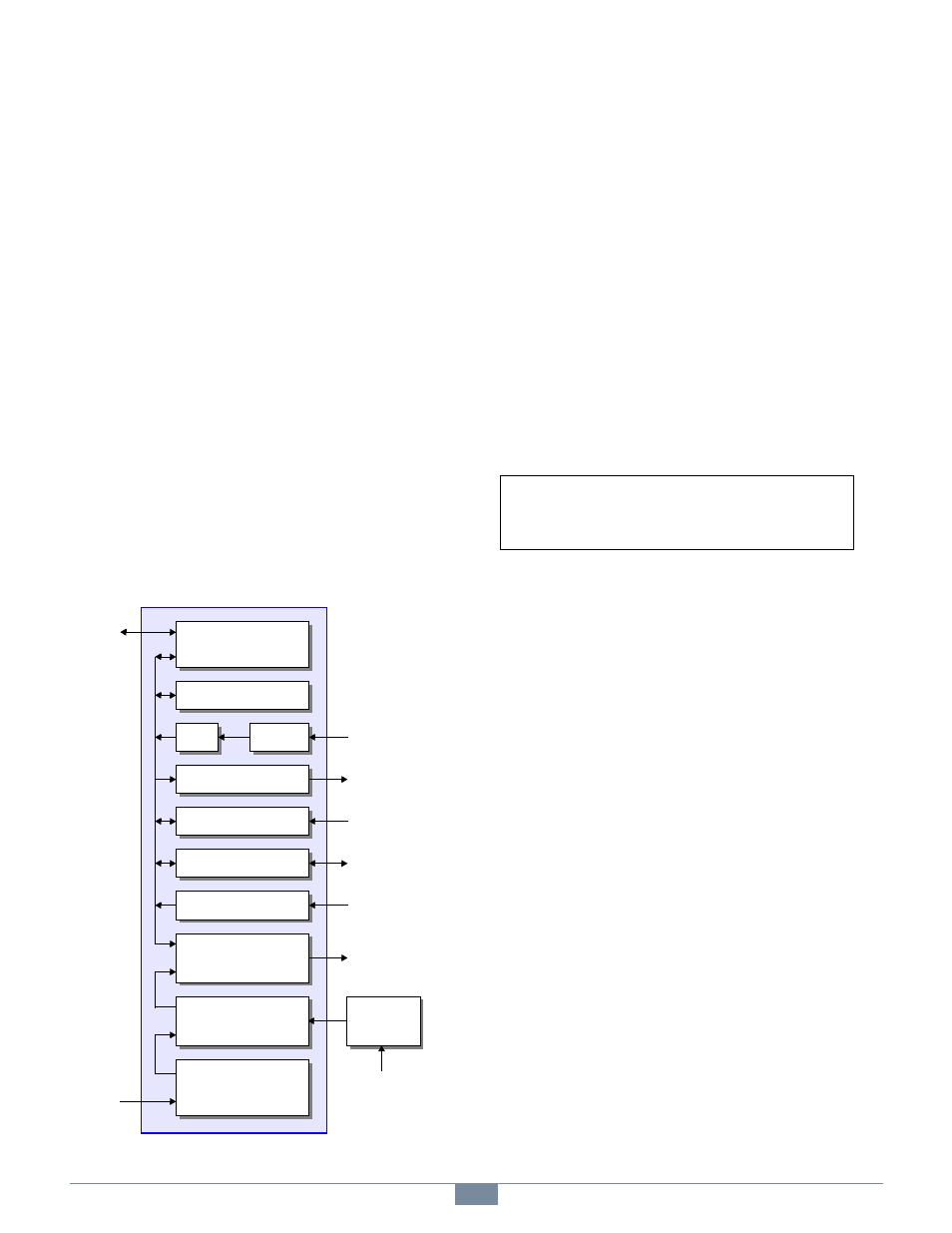
Figure 1: Block Diagram of the 2426 Module
A typical system consists of one or more 2426 modules, one or
more associated power supplies, a host computer running a
control and/or monitoring program, and a local area network
(LAN).
In the simplest case, the LAN may consist of a crossover cable
that connects a host directly to a single 2426 module. In more
complex systems, each 2426 module will typically connect to a
network switch or router, which in turn provides access to the
module from one or more host computers.
2.2 Status LEDs
Numerous LEDs reside on the module to give a comprehensive
visual indication of the state of the module and its various
interfaces. Each LED is labeled on the module silkscreen to
indicate its function.
2.3 Heartbeat
A “heartbeat” LED flashes several times per second as an
indication that the module’s internal CPU is functional and
various other resources are operating within error limits.
HBT lights periodically to indicate the module’s internal
control systems are operating normally.
2.4 Module Reset
2.4.1 RST Pushbutton
The module will immediately execute a hardware reset when
the RST pushbutton is pressed.
RST lights briefly while the module is being reset.
2.4.2 CONFIG Pushbutton
The module will enter its Configuration mode if the CONFIG
pushbutton is pressed while RST is pressed and then released.
While in the Configuration mode, the module’s network
interface assumes a known MAC address and its servers listen
at all IP addresses. See Chapter 1 for details.
CONFIG lights when the module is in Configuration
mode.
ADC
Mux
Encoder Interface
DAC
Digital Inputs
Digital Outputs
Interlock Routing
Serial RS-422/485
Ethernet
Power Supplies
CPU
Interlock
Contacts
24VDC
16 Digital Out
LAN
8 Digital In
Serial COM
Incremental
Encoder
Analog Out
6 Analog In
Auxiliary
Power
This symbol is placed next to descriptions of
the module’s LED status indicators.