3 hardware configuration, 1 example – Sensoray 2426 User Manual
Page 12
2426 Instruction Manual
10
Digital Output Interface
Figure 11: Recommended Load Wiring
Load impedance must be high enough to limit
current on the DOUT terminals to their
maximum allowed values. See “Digital Output
Interface Specifications” on page 15 for details.
In particular, do not short +DOUT to -DOUT
as this may damage module circuitry.
7.2.1.1 Output Pull-Ups
The module’s DOUT channel circuits do not have resistors that
will pull up -DOUT to the +DOUT potential when a channel is
turned off. If a load requires a pull-up resistor, it must be
supplied externally as shown in Figure 12.
Figure 12: Load With External Pull-up
7.2.1.2 Wired-or Operation
The DIO channel output driver is an open-collector transistor,
thus it is possible to “wire-or” a channel by connecting its
-DOUT terminal to one or more external open-collector
drivers. If any driver asserts its active-low output, the channel
will be driven to its active state.
7.3 Hardware Configuration
Each channel, or in some cases each group of three channels, is
associated with a block of configuration programming posts in
the Interlock Power Routing Matrix (IPRM). See Figure 2 for
the location of the IPRM. Channels 0 to 6 have a dedicated
configuration block per channel, while channels 7 to 9 share a
common block, as do channels 10 to 12, and 13 to 15.
Each block of posts has six shunt positions, corresponding to
the six signals on the internal power bus. Only one shunt
should be installed per block. If a channel will not be used, it is
not necessary to install a shunt on its configuration block.
For each channel that will be used, a shunt must be installed on
its configuration block to connect its +DOUT terminal to a
positive DC voltage supply. This establishes the high side
voltage for the channel and enables the built-in protection
diode to suppress induced EMF from inductive loads. Also, in
cases where the selected power signal is sourced through an
interlock contact (e.g., emergency stop switch, oven door
interlock), the channel will automatically power down its load
when the interlock contact is open.
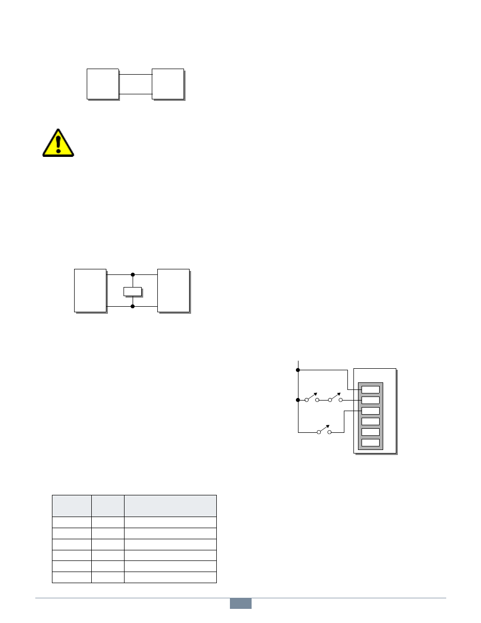
7.3.1 Example
Figure 13 illustrates a system in which:
• PWR1 receives power through two series-connected
emergency stop contacts. Any DIO that is configured to
use PWR1 (i.e., a shunt is installed on its IPRM at pins
3-4) will deactivate if either ESTOP contact is open.
• PWR2 receives its power through a safety interlock
contact on an oven door. Any DIO that is configured to
use PWR2 (i.e., a shunt is installed on its IPRM at pins
5-6) will deactivate when the oven door is open.
All DIOs configured to use the +24V “always on” power
source will be unaffected by interlock contacts. PWR3, PWR4
and PWR5 are not used in this application, and so are left
disconnected.
Figure 13: Wiring Example With Interlocks
Table 5: Shunt Placement on an IPRM Block
PWB
Label
Shunt
Pins
Selected Power Source
+24V
1-2
+24V power, always on.
PWR1
3-4
Optional positive DC power #1.
PWR2
5-6
Optional positive DC power #2.
PWR3
7-8
Optional positive DC power #3.
PWR4
9-10
Optional positive DC power #4.
PWR5
11-12
Optional positive DC power #5.
+DOUT
-DOUT
2426 DOUT
Connector
+
-
Load
+DOUT
-DOUT
2426 DOUT
Connector
+
-
Load
Res
PWR5
PWR4
PWR3
PWR2
PWR1
+24V
2426
TB
+24V
EStop
EStop
Oven Door
Interlock