5 safety features, 6 timestamps, 7 module layout – Sensoray 2426 User Manual
Page 5: 3 module state upon reset, 1 connectors
2426 Instruction Manual
3
Introduction
2.4.3 Module State Upon Reset
Upon power-up, or in response to a hardware or software reset,
all module outputs are forced to known states:
• All DOUTs are all set to their inactive states and are
configured to operate in the Standard (vs. PWM) operating
mode.
• AOUT is set to zero volts out.
• The COM interface ceases transmit operations and all
communication queues are flushed.
2.5 Safety Features
Model 2426 features several special mechanisms that can be
used to enhance the safety of application systems:
• A hardware watchdog timer forces a hardware reset in the
event of a malfunction by the module’s internal CPU, thus
forcing all outputs to their “safe” states.
• A communication watchdog timer generates a software
reset if a network client ceases to communicate, thus
forcing all outputs to their “safe” states.
• All DOUTs incorporate interlock chaining to ensure
fail-safe shutdown when associated safety interlock
contacts are open. By implementing this essential
function within the module, system complexity and cost is
reduced due to reduction of wiring and external
termination boards.
2.6 Timestamps
A high-resolution timestamp generator is implemented on the
module to circumvent some of the timing limitations incurred
when passing real-time data over networks.
A timestamp value is attached to all encoder and analog input
data so that the application can know when sampled data was
acquired.
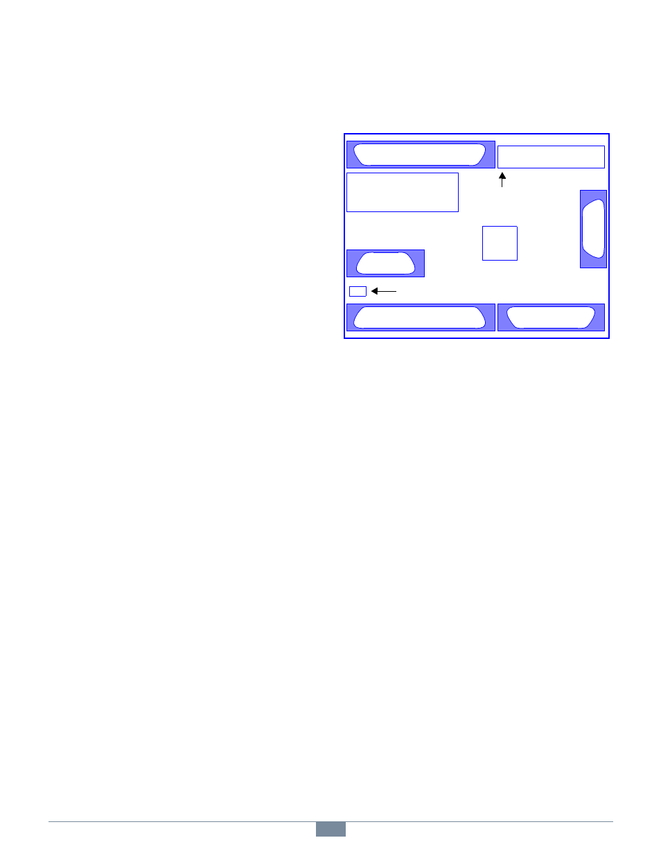
2.7 Module Layout
Figure 2 shows the locations of all application connectors and
user-installed configuration posts on the module.
Figure 2: Module Layout
2.7.1 Connectors
The connectors in Figure 2 are abbreviated as follows:
• AIO — Analog inputs and output.
• COM — Serial RS-422/RS-485 communication port.
• DIN — General purpose digital inputs.
• DOUT — General purpose digital outputs.
• ENC — Incremental encoder interface.
• ETH — Ethernet interface.
• TB — Power terminal block.
The 2426 module incorporates robust, two-piece mating
connectors for field wiring (see Figure 2). All connectors have
mechanical detentes or provision for hold-down fasteners to
help maintain solid connections in high-vibration
environments. Except for the power TB, mating connectors are
not supplied with the module.
Several connectors are reserved for manufacturing and test.
Applications should not make electrical connections to these
connectors: JP11, P3 and P5. Also, a shunt must be installed at
JP12; it is removed only for factory programming and test.
ETH
TB - Power
Interlock Power
Routing Matrix (IPRM)
COM
ENC
AIO
DOUT
DIN
Pin 1
COM Configuration Posts