Chapter 8: digital input interface, 1 overview, 2 din connector – Sensoray 2426 User Manual
Page 13: 1 debounce, 2 state indicators
2426 Instruction Manual
11
Digital Input Interface
Chapter 8: Digital Input Interface
8.1 Overview
Eight general purpose digital input (DIN) channels are
available on the 2426 module, numbered 0 to 7.
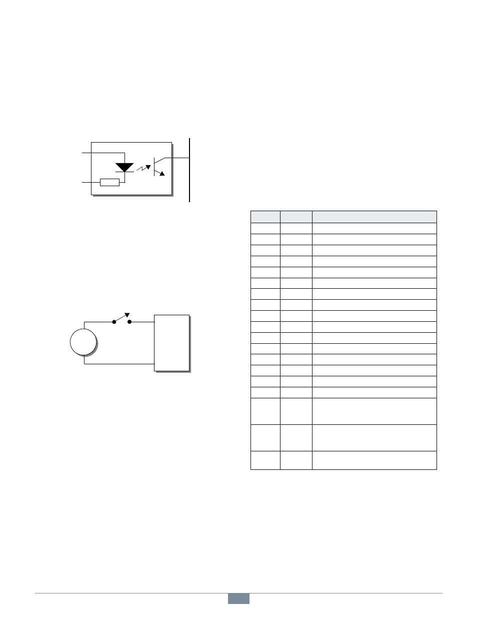
Figure 14: DIN Channel Block Diagram
As shown in the simplified block diagram of Figure 14, each
DIN channel has an input circuit consisting of a resistor and
LED connected in series. When a sufficiently large DC voltage
is applied across the input—thus driving current through the
LED—the channel switches to its on state. The channel is off
when no current is flowing through the LED.
Figure 15: Typical Application
8.1.1 Debounce
The module’s internal CPU periodically samples the DIN
channels. As each new channel sample is captured, it is stored
in a ring buffer. The ring buffer accumulates samples over a
debounce interval that spans multiple sample periods. Every
sample period, the CPU computes a debounced state for each
channel based on the contents of its ring buffer. After changing
state, an input signal must maintain a steady state for at least
the debounce interval in order for the state change to register as
debounced data.
Network clients can access both the raw (non-debounced) and
debounced DIN states, as required by the application. Raw
states are captured on demand when requested by a client.
Debounced states are delayed by the debounce interval plus up
to one sample period.
8.1.2 State Indicators
One state indicator is provided per channel to indicate the
debounced input signal level for that channel:
DIN 0-7 - Each of these will light when current is driven
through its associated channel inputs by an external signal
generator.
8.2 DIN Connector
Digital input connections are made through the 37-pin DIN
connector (see Figure 2).
4.7K
I
n
t
e
r
n
a
l
D
a
t
a
B
u
s
+DIN
-DIN
+DIN
-DIN
24V
+
-
2426 DIN
CONNECTOR
Table 6: DIN Connector Pin Assignments
Pin
Name
Function
20
+DIN0
DIN channel 0 positive input
2
-DIN0
DIN channel 0 negative input
22
+DIN1
DIN channel 1 positive input
4
-DIN1
DIN channel 1 negative input
24
+DIN2
DIN channel 2 positive input
6
-DIN2
DIN channel 2 negative input
26
+DIN3
DIN channel 3 positive input
8
-DIN3
DIN channel 3 negative input
28
+DIN4
DIN channel 4 positive input
10
-DIN4
DIN channel 4 negative input
30
+DIN5
DIN channel 5 positive input
12
-DIN5
DIN channel 5 negative input
32
+DIN6
DIN channel 6 positive input
14
-DIN6
DIN channel 6 negative input
34
+DIN7
DIN channel 7 positive input
16
-DIN7
DIN channel 7 negative input
1,3,5,7,9,
11,13,15,
17
+24VOUT
+24V outputs, referenced to GND. These can be
used to power modest external loads.
21,23,25,
27,29,31,
33,35
GND
System GND reference.
18,19,
36,37
NC
Not connected. These are uncommitted pins,
reserved for future use.