5 dc voltage sources, 6 thermocouples, 7 strain and pressure gages – Sensoray 618 User Manual
Page 9
Sensoray Model 618/619 Smart A/D
7
Sensor Connections
Thermistors have much higher resistance values than
RTDs over most of their operating range. Consequently,
the two-wire circuit may be used if your sensor will be
operating exclusively at high resistance values. However,
if your thermistor will be operating at lower resistance
values, you should consider implementing a three-wire or
four-wire circuit to reduce or eliminate cable-loss errors.
4.5 DC Voltage Sources
DC voltage sources are connected directly to the V+ and
V- terminals. DC voltage sources should never be
connected to the I+ or I- terminals.
Since all voltage input ranges are bipolar, DC voltages
may be connected in either signal polarity. Although the
diagram below shows Voltage+ connected to V+ and
Voltage- connected to V-, there is no reason that
Voltage+ must be positive with respect to Voltage-.
DC voltage connection
4.5.1 Recommended Practice
In order to assure accurate DC voltage measurements,
high common-mode voltages (CMV) must not be
permitted to appear on V+ or V-.
If your signal source is isolated (i.e., sourced from a
battery or isolated power supply), you can connect V+ or
V- to either S or the backplane power supply return. This
connection can be implemented as a direct short or can be
made through, for example, a 10K
Ω
resistor. There
should be no significant DC current flowing through this
connection; its purpose is to limit the common-mode
voltage at the sense inputs.
In the case of low source impedance voltage sources,
another way to limit CMV is to install the channel signal
conditioning circuit as described in Section 3.
4.6 Thermocouples
Thermocouple (TC) signals are connected directly to the
V+ and V- terminals. TCs should never be connected to
the I+ or I- terminals.
TC wires are color coded to indicate polarity. The red
thermocouple wire is always negative, by convention.
The positive TC wire should always be connected to the
V+ terminal, and the negative wire should always be
connected to the V- terminal.
Thermocouple connection
4.6.1 Recommended Practice
A TC reference-junction compensation sensor is required
in order to obtain accurate TC measurements. This
sensor is present on all Sensoray Smart A/D termination
boards.
If you will be using a TB of your own design, you should
physically arrange the compensation sensor so that it is
thermally coupled to the TC reference junctions.
Significant measurement errors can occur if you allow
the TB to be exposed to thermal transients, such as air
flows from cooling fans or ambient breezes. For best
results, the TB should be located within a protective
enclosure after sensor terminations have been made.
If your TC is ungrounded, always enable the channel
signal conditioning circuit. See “Configuration” on
page 3 for details.
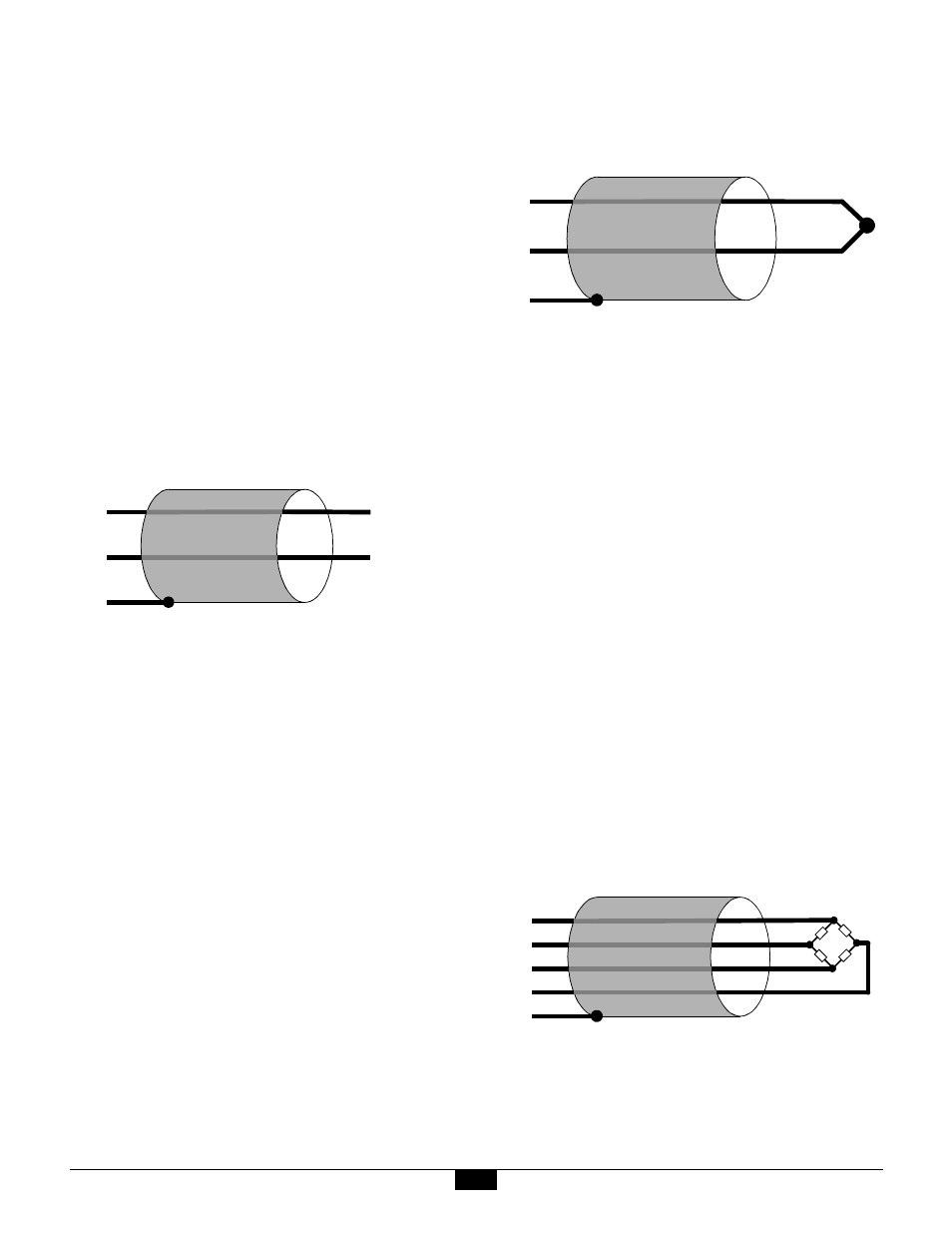
4.7 Strain and Pressure Gages
In a typical strain/pressure gage sensor, four wires are
used to connect the gage to the sensor channel. Two of
the wires supply gage excitation, while the other two
wires transport the gage output signal to the Smart A/D
measurement circuitry.
Strain/pressure gage connection
4.7.1 Recommended Practice
Due to the high measurement gain used, strain and
pressure gages should use shielded cable. The shield
should be connected only to the channel S terminal.
V +
V –
S
Voltage +
Voltage –
V +
V –
S
RED
V +
I +
V –
I –
S