Sensor connections, 2 connector pinouts, 3 sensor channels – Sensoray 618 User Manual
Page 7: 4 sensor connections, 1 overview, P2 p3
Sensoray Model 618/619 Smart A/D
5
Sensor Connections
4 Sensor Connections
4.1 Overview
Sensors are connected to the Smart A/D by means of
40-pin headers P2 and P3.
4.1.1 Termination Boards
It is recommended that sensors be connected to the Smart
A/D board by means of optional screw termination
boards (TB), such as Sensoray models 7409TB or
7409TC. These termination boards integrate
reference-junction sensors for thermocouples and are
designed to mate directly to Smart A/D board headers P2
and P3.
4.1.2 Sensor Hot Insertion
Sensors may be electrically connected and disconnected
from the Smart A/D or termination board without
removing the Smart A/D board or power from the
backplane.
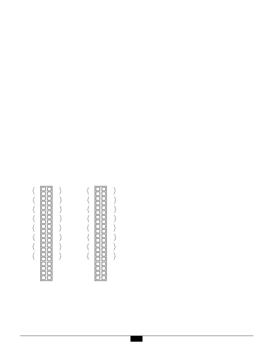
4.2 Connector Pinouts
Show here are the pin assignments for headers P2 and P3:
Sensor channels 0 through 7 connect to header P2.
On model 619 only, sensor channels 8 through 15
connect to header P3. Although it may be present on the
model 618, header P3 is not used
4.2.1 Reference Junction Sensor
Three of the signals shown near the bottom of the above
header diagrams—+12V, GND and TREF—are used for
interfacing the Smart A/D to a remote thermocouple
reference-junction temperature sensor. One such sensor
is provided on all models of Sensoray Smart A/D
termination boards.
The +12V and GND signals provide excitation to the
reference sensor. The TREF connection provides a path
from the sensor output to a dedicated input channel on
the Smart A/D board.
If you are using thermocouples in your application and
you will be implementing your own termination system,
you must provide your own remote temperature sensor.
The sensor, which produces an output of 10mV/°K, must
have its output signal routed to the TREF pin.
4.3 Sensor Channels
Each sensor channel provides five signals for interfacing
to a sensor. A sensor can have as many as five
connections to a channel channel, or as few as two.
4.3.1 Sense Terminals
Two of the channel signals, designated V+ and V-, are
universally used for all sensor types. These two signals
are, respectively, the positive and negative differential
voltage sense inputs.
Since the sense inputs accept differential signals, it is not
required for either of the two input signals to be at ground
potential. The Smart A/D digitizer measures only the
difference voltage across the two sense inputs.
Due to common-mode voltage (CMV) input constraints,
however, you must ensure that neither sense input, with
respect to system ground, exceeds the maximum input
CMV permitted by the Smart A/D.
Small excursions beyond the CMV limit may degrade
measurement accuracy on the offending channel, while
large excursions may cause measurement errors on other
sensor channels, or worse yet, damage the board.
See “General Specifications” on page 19 for input CMV
limit values.
1
2
10
11
14
15
12
13
16
17
18
19
3
4
5
6
7
8
9
20
21
24
25
22
23
26
27
28
29
30
31
34
35
32
33
36
37
38
39
40
V+
V-
Ch0
I+
I-
Ch0
V+
V-
Ch1
I+
I-
Ch1
V+
V-
Ch2
I+
I-
Ch2
V+
V-
Ch3
I+
I-
Ch3
V+
V-
Ch4
I+
I-
Ch4
V+
V-
Ch5
I+
I-
Ch5
V+
V-
Ch6
I+
I-
Ch6
V+
V-
Ch7
I+
I-
Ch7
GND
GND
N.C.
TREF
SHIELD
+12V
GND
SHIELD
1
2
10
11
14
15
12
13
16
17
18
19
3
4
5
6
7
8
9
20
21
24
25
22
23
26
27
28
29
30
31
34
35
32
33
36
37
38
39
40
V+
V-
Ch8
I+
I-
Ch8
V+
V-
Ch9
I+
I-
Ch9
V+
V-
Ch10
I+
I-
Ch10
V+
V-
Ch11
I+
I-
Ch11
V+
V-
Ch12
I+
I-
Ch12
V+
V-
Ch13
I+
I-
Ch13
V+
V-
Ch14
I+
I-
Ch14
V+
V-
Ch15
I+
I-
Ch15
GND
GND
N.C.
TREF
SHIELD
+12V
GND
SHIELD
P2
P3