Calibration, 6 calibration, 1 calibration procedure – Sensoray 618 User Manual
Page 17
Sensoray Model 618/619 Smart A/D
15
Calibration
6 Calibration
Smart A/D boards are factory calibrated to meet or
exceed published specifications. Because the board
employs high-stability standards, calibration should not
be necessary unless the board has been subjected to
environmental extremes or has been in service for an
extended time period.
WARNING: RECALIBRATION AFFECTS THE
ACCURACY OF ALL SENSOR MEASUREMENTS.
After calibrating a Smart A/D board, you can’t “undo”
the new calibration. The only way to correct a
calibration error is to perform another calibration.
6.0.1 User-supplied References
To perform a board calibration, you must supply the
following external reference standards:
• 5.0000V signal.
• 500.00mV signal
• 380.00
Ω
resistor.
The actual values of your standards may deviate from
these target values by up to ±1%, but the values must be
stable and precisely known.
6.0.2 Calibrate
This API function calibrates one of the Smart A/D
internal reference standards and stores the calibration
value in non-volatile memory on the Smart A/D board.
Although this function returns a value, the value is only
of use for factory test purposes and should therefore be
ignored by your application.
The RefValue argument is used to specify the exact
value of the user-supplied reference. As mentioned
earlier, the absolute value of the reference is not critical,
but knowledge of the exact reference value is required.
ChannelNumber
specifies the sensor channel number
that is connected to the user-supplied reference. You
may use any sensor channel of your choosing.
The StdNum argument specifies which of the external
references is supplied to the target channel and the
measurement range to be used for the calibration.
6.1 Calibration Procedure
6.1.1 Order of Calibration
Three invocations of the Calibrate function are necessary
to completely calibrate the Smart A/D board. These
invocations must occur in the order shown in Table 4,
from top to bottom.
Specifically, the 5V standard is calibrated first, followed
by the 500mV standard and then the resistance standard.
6.1.2 Calibration Process
Each measurement range is calibrated by following a
five-step procedure:
1. Connect the appropriate external reference standard,
as specified in Table 4, to the target channel. In the
case of the reference resistor, you must use a
four-wire connection to the resistance standard.
1. Configure the target channel’s sensor type as
specified under Measurement Range in Table 4. This
is done by calling the SetSensorType function with
the appropriate sensor definition code.
2. Allow sufficient time for sensor data to stabilize on
the target channel. A simple way to do this is to poll
the target channel’s sensor data, using the
GetSensorData function, until non-zero data is
returned.
3. Invoke the Calibrate command, using the StdNum
value from Table 4, then wait for the return value.
4. Reset the Smart A/D board. This is normally
accomplished by invoking the ResetBoard function.
Arguments:
ChannelNumber
StdNum
RefValue
Returns:
Ignore
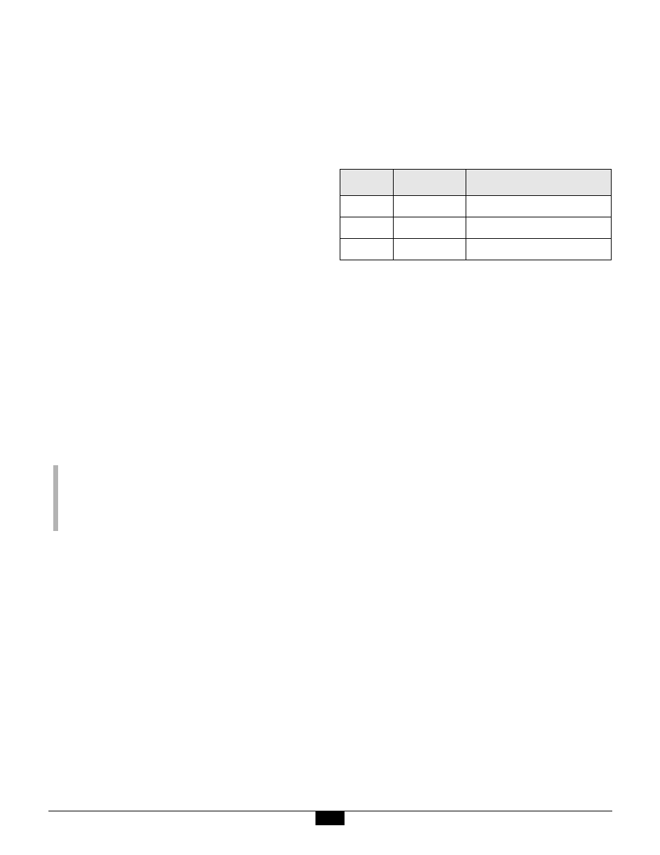
Table 4: StdNum Values for the Calibrate Function
StdNum
Reference
Measurement Range
0
5.0000 V
±5V, 200uV resolution
1
500.00 mV
±500mV, 20uV resolution
2
380.00
Ω
400
Ω
, 0.02
Ω
resolution